Functional description 5 – Lukas Compact Units User Manual
Page 9
9
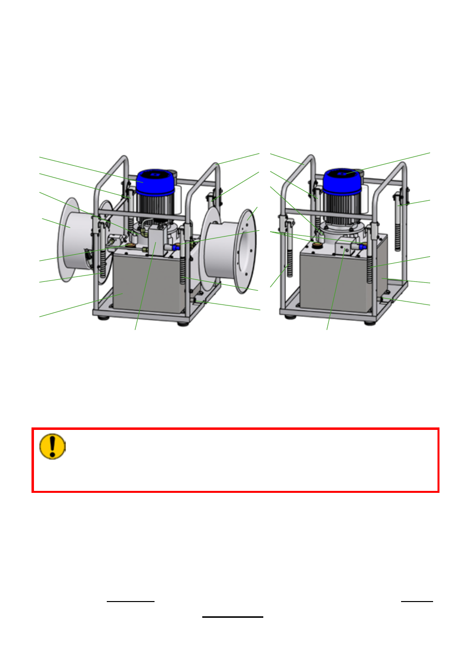
The main components (see example illustration) of a LUKAS hydraulic unit are:
Functional description
5.
5.1 General
CAUTION!
Where multiple implements are operated with the same hydraulic unit, it must be
ensured that the usable volume of hydraulic fluid in the fluid reservoir is greater
than the maximum possible operating fluid volume required for all connected
implements combined.
If no external control unit (e.g. control desk) is to be connected, it is possible to order a LUKAS
hydraulic unit with the valves or valve blocks directly attached.
If you are considering these optional valves or valve blocks, you should consult your
authorised LUKAS dealer or LUKAS directly before you combine your rerailing equipment
components. Only then can you be sure that the individual, combinable LUKAS components
(unit, implements, etc.) of your system arrangement will continue to function correctly, and
that risks to persons and equipment are eliminated.
Operation without an attached or external control unit is NOT
permitted.
1 Fluid reservoir
2 Motor
3 Pump
4 Frame
5 Connecting block
As a general principle on all LUKAS hydraulic units, a hydraulic pump is operated with a
motor (combustion engine or electric motor) that feeds the fluid from the reservoir and builds
up the pressure. The fluid distribution is then controlled by valves directly attached to the
equipment or by external control units (e.g. control desks).
The mounted frame serves as a simple protective cage and as a mounting base for
accessories that can be fitted. The hydraulic unit can also be carried by the frame or using
carrying handles mounted on it.
6 Valve block
7 Carry handles
8 Fluid drain plug
9 Filler cap
10 Optional hose reel attachment
1
2
3
7
8
9
10
1
2
3
4
5
6
7
9
10
7
7
7
7
8