AEM Infinity Supported Applications - Honda H-Series Engine User Manual
Page 14
14
© 2014 AEM Performance Electronics
Infinity
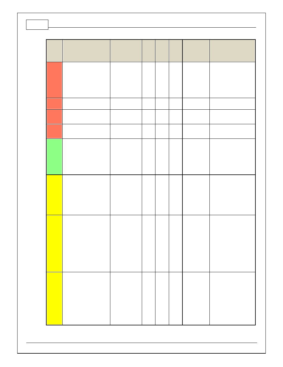
Pin
Hardware Reference
7100-XXXX-62
7101-XXXX-63
Function
Dest.
Pin
Honda
OBD 1
Dest.
Pin
Honda
OBD
2a
Dest.
Pin
Honda
OBD
2b
Hardware
Specification
Notes
C2-29
LowsideSwitch_9
Tachometer
A19
Lowside switch,
4A max with
internal f ly back
diode, 2.2K 12V
pullup. Inductiv e
load should NOT
hav e f ull time
power.
See Setup Wizard page
Tacho f or conf iguration
options.
C2-30
AGND_2
Sensor Ground
Dedicated
analog ground
Analog 0–5V sensor ground
C2-31
AGND_2
Sensor Ground
Dedicated
analog ground
Analog 0–5V sensor ground
C2-32
AGND_2
Sensor Ground
Dedicated
analog ground
Analog 0–5V sensor ground
C2-33
Analog_In_20
Spare Analog Input
12 bit A/D, 100K
pullup to 5V
0–5V analog signal. Use +5V
Out pins as power supply
and Sensor Ground pins as
the low ref erence. Do not
connect signals ref erenced
to +12V as this can
permanently damage the
ECU.
C2-34
Analog_In_21
3 Step Enable
Switch
12 bit A/D, 100K
pullup to 5V
0–5V analog signal. Use +5V
Out pins as power supply
and Sensor Ground pins as
the low ref erence. Do not
connect signals ref erenced
to +12V as this can
permanently damage the
ECU. See 3StepSwitch 1-
axis table f or setup.
C2-35
Analog_In_22
USB Logging
Activ ate
12 bit A/D, 100K
pullup to 5V
0–5V analog signal. Use +5V
Out pins as power supply
and Sensor Ground pins as
the low ref erence. Do not
connect signals ref erenced
to +12V as this can
permanently damage the
ECU. See
USBLoggingRequestIn
channel f or input state. See
Setup Wizard page USB
Logging f or conf iguration
options.
C2-36
Analog_In_23
Charge Out
Pressure
12 bit A/D, 100K
pullup to 5V
0–5V analog signal. Use +5V
Out pins as power supply
and Sensor Ground pins as
the low ref erence. Do not
connect signals ref erenced
to +12V as this can
permanently damage the
ECU. See ChargeOutPress
[kPa] channel f or input state.
See Setup Wizard page
Charge Out Pressure f or
calibration options.