Air discharge moisture drain, Figure 4-11: typical discharge drain, Table 4-12: tubing size vs. color – Hale CAFS Attack User Manual
Page 37
37
CAFS Air Bottle Installer/Operation Guide
p/n: 029-0020-85-0
In s talle r In sta llatio n
❑
3. A method for discharge draining / flushing (possible tee fitting) must also be
provided. (See heading “ Air Discharge Moisture Drain” on page 37.)
4. Use a suitable sealing compound (for example, Loctite PST) on all fitting
threads.
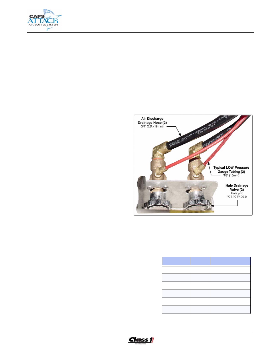
Air Discharge Moisture Drain
(See Figure 4-11: “Typical Discharge Drain.”)
The installer/
builder must sup-
ply individual
moisture drain
lines and valving
(3/4” / 9.5 mm),
along with all nec-
essary DOT
approved tubing
(3/8” / 10 mm)
from the low pres-
sure air inject
hose lines to pre-
vent freezing in
cold weather.
When designing
the drain system
care must be
taken to prevent
contamination of the air and water system with foam and vise versa. Use
appropriate check valves in the drain lines. Also see Figure 4-10: “Typical
LOW Pressure CAFS Air Connections” on page 36.
All Hale supplied tubing con-
forms to the color scheme
listed in Table 4-12: “Tubing
Size vs. Color.”
Use a suitable sealing com-
pound (for example, Loctite
PST) on all fitting threads.
Figure 4-11: Typical Discharge Drain
Line Size
Color
Use
1/4” (6.4mm)
Black
Air
1/4” (6.4mm)
Green
Air
1/4” (6.4mm)
Red
Air
3/8” (9.5mm)
Blue
TPM
3/8” (9.5mm)
Orange
Manifold Drain
3/8” (9.5mm)
Yellow
Main Pump Drain
Table 4-12: Tubing Size vs. Color