Intake air pressure gauge layout option, Low pressure cafs connect (2) – Hale CAFS Attack User Manual
Page 35
35
CAFS Air Bottle Installer/Operation Guide
p/n: 029-0020-85-0
In s talle r In sta llatio n
❑
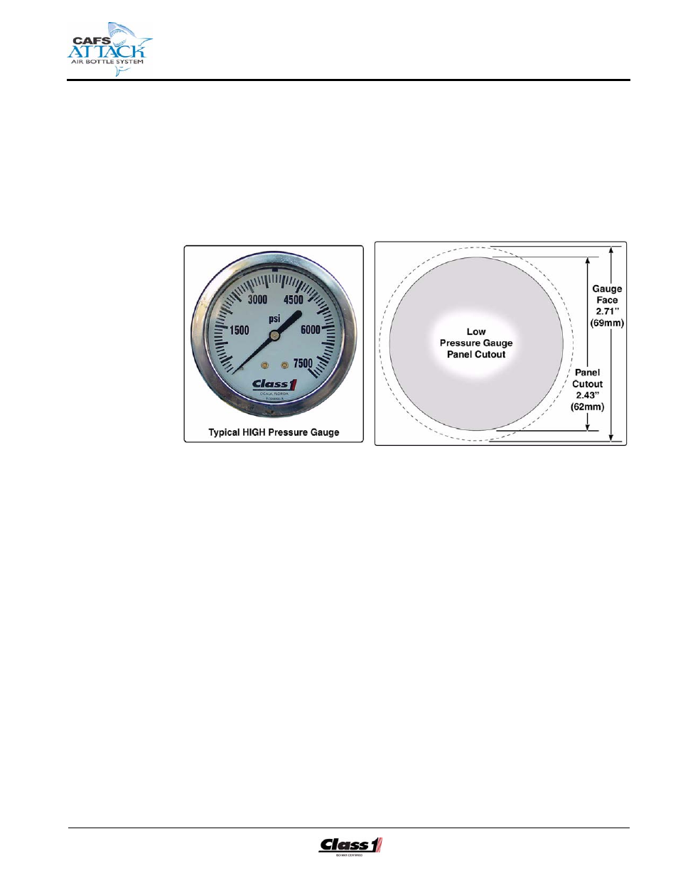
Intake Air Pressure Gauge Layout Option
An “optional” high pressure gauge is available,
Class1 p/n: ??
, to provide
accurate intake air pressure monitoring (up to 7,500 PSI / 517 BAR) during
system operation and cylinder tank refill. (See Figure 4-9: “Typical Intake
Air Pressure Gauge Layout.”)
Figure 4-9: Typical Intake Air Pressure Gauge Layout
The gauge should be mounted in the area of the CAFSAttack operator’s
panel (tank refill connector) and plumbed before the air supply shut-off valve
intake. Provisions must also be made for the pressure transducer.
Also see WARNING ! note beginning on page 32. Use a suitable sealing
compound (for example, Loctite PST) on the fitting threads.
Low Pressure CAFS Connect (2)
A LOW or CAFS air pressure hose line (one each) and injection check
valves (one each) must be plumbed from each electrically-operated shut-off
valve connection to the CAFSAttack discharge manifold air intake port.
(See Figure 4-10: “Typical LOW Pressure CAFS Air Connections,” on page
36.)
1. The installer/builder must provide the necessary plumbing hose and hardware,
i.e., 3/4” (19 mm) fittings, tubing, etc. and make certain they conform to the
maximum CAFS system operating pressure of 150 PSI (10 BAR).