6 svs discharge manifold, Svs discharge manifold – Hale CAFS Attack User Manual
Page 30
❑ Installer Installation
30
CAFS Air Bottle Installer/Operation Guide
p/n: 029-0020-85-0
2.
Consideration must be given for routing the HIGH pressure tubing /
hoses and electrical harnesses. Make certain there is sufficient room
behind the assembly. If necessary, order a longer or shorter harness to
suit the location demands.
3.
Modify the apparatus operator’s control panel to accept the CAFSAttack
operator’s panel and placard. (See Figure 4-4: “Operator’s Panel Layout
Dimensions.”) Use #10-24 screws and hardware to secure the panel the
apparatus control panel.
4.
For plumbing, proceed to heading 4.7 “Plumbing” on page 31. For elec-
trical, proceed to heading 4.8 “Electrical” on page 38.
4.6
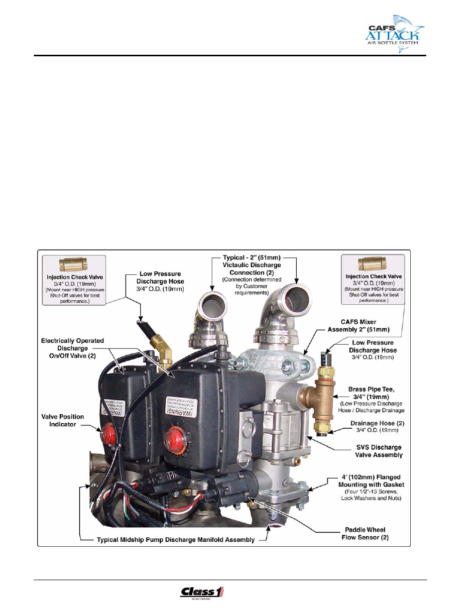
SVS DISCHARGE MANIFOLD
Figure 4-5: Typical CAFSAttack SVS Discharge Manifold Assembly