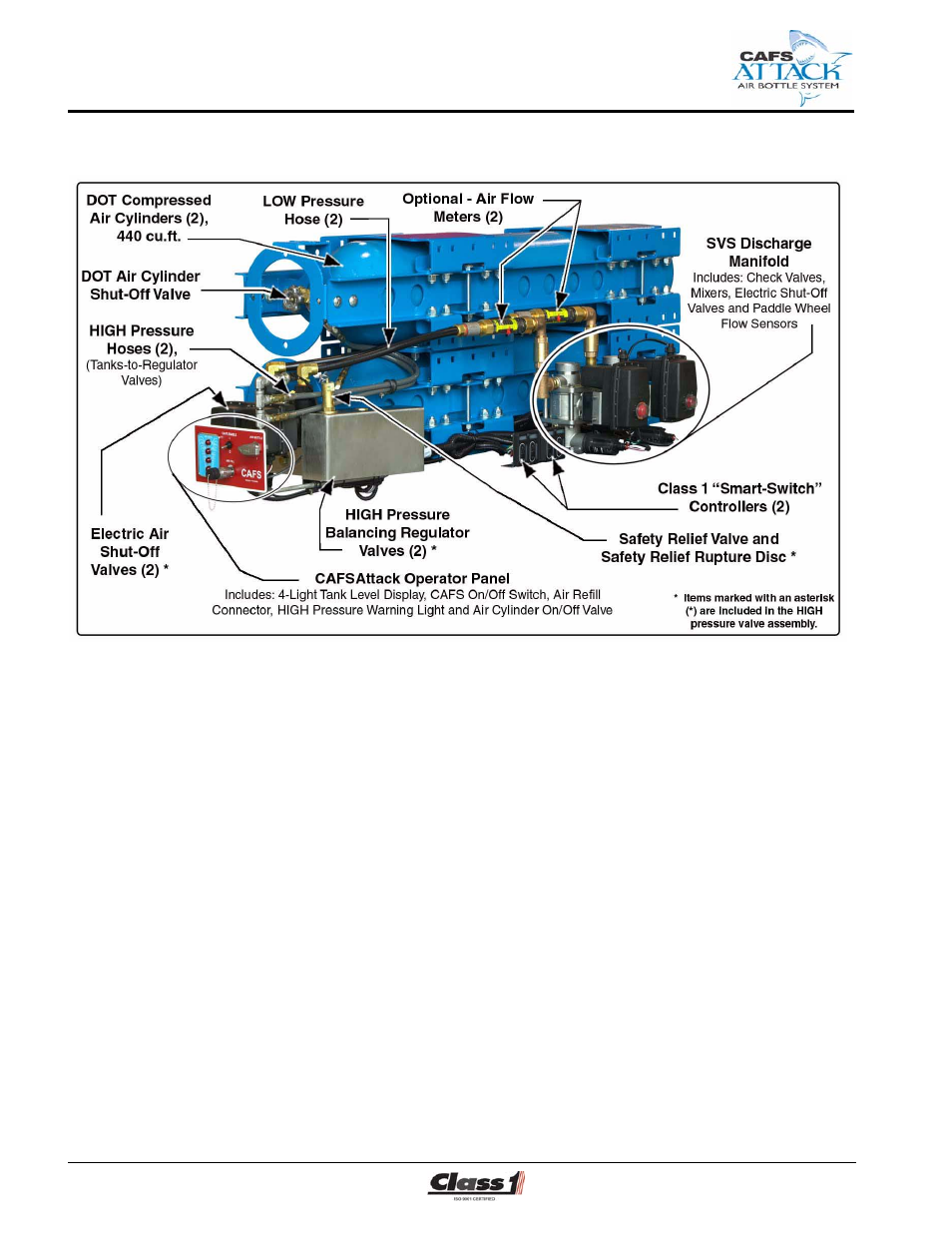
Figure 2-1: cafsattack system overview – Hale CAFS Attack User Manual
Page 16
❑ Description
16
CAFS Air Bottle Installer/Operation Guide
p/n: 029-0020-85-0
Figure 2-1: CAFSAttack System Overview
❑
HIGH pressure valve assembly - continued
●
Tee-type air filter - used to remove any particulate contaminates from
the system. A multi-layered glass fiber element produces high effi-
ciency silt-control filtration and provides for extended service intervals
and reduced maintenance cost.
A visual pressure indicator enables the operator to read contaminated
build up before the element is plugged, with an automatic reset.
●
Two electrically-controlled open/close air shut-off valves.
●
Pressure safety relief valve, set at 165 PSI (11.4 BAR).
●
Pressure safety relief Rupture Disc, set at 350 PSI (24 BAR).
●
Check valves to ensure separation of water, foam solution, foam con-
centrate and air.
❑
Discharge Manifold
●
Two electrically-controlled shut-off valves, with valve position
indicator.
See separate SVS manual provided (Hale p/n: 209-0020-90-0) for
additional valve information.
●
Mixing chambers.