5 cafsattack operator panel layout, Figure 4-4: operator’s panel layout dimensions, Cafsattack operator panel layout – Hale CAFS Attack User Manual
Page 29
29
CAFS Air Bottle Installer/Operation Guide
p/n: 029-0020-85-0
In s talle r In sta llatio n
❑
Note: For CAFSAttack systems, the main cable harness included with the Foam-
Logix system differs from what is shown in the FoamLogix manual. For an over-
view of the replacement cable used with CAFSAttack, see Section 7, “Drawing /
Manual Package” on page 67.
4.5
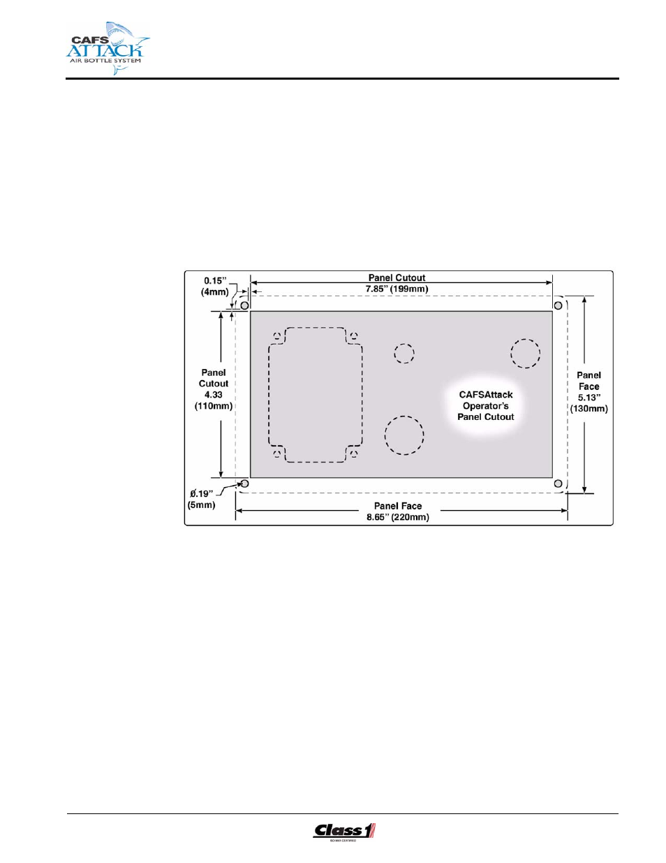
CAFSATTACK OPERATOR PANEL LAYOUT
(See Figure 4-4: “Operator’s Panel Layout Dimensions.”)
Figure 4-4: Operator’s Panel Layout Dimensions
The following components are pre-mounted on the CAFSAttack operator’s
panel assembly:
❑
Inteli-Tank high pressure air level indicator - four (4) RED indicator lights
❑
HIGH pressure WARNING ! indicator light (YELLOW)
❑
On/Off air enable switch
❑
HIGH pressure shut-off valve and handle
❑
Quick-connect HIGH pressure air cylinder refill connection
Also see Figure 2-3: “CAFSAttack Operator Control Panel” on page 21.
1.
Determine the location on the apparatus operator’s control panel for the
CAFSAttack operator’s panel assembly, with placard. This assembly
must be located at the main pump operator’s position in close proximity
to the FoamLogix system controls.