3 spc smart-switch controller, Figure 6-3: spc connector arrangement, Table 6-4: spc connector assignments – Class1 EZFill Foam Refill User Manual
Page 38
Service, Maintenance & Troubleshooting
❑
35
EZFill Installer / User Guide, p/n: 029-0020-82-0
6.3
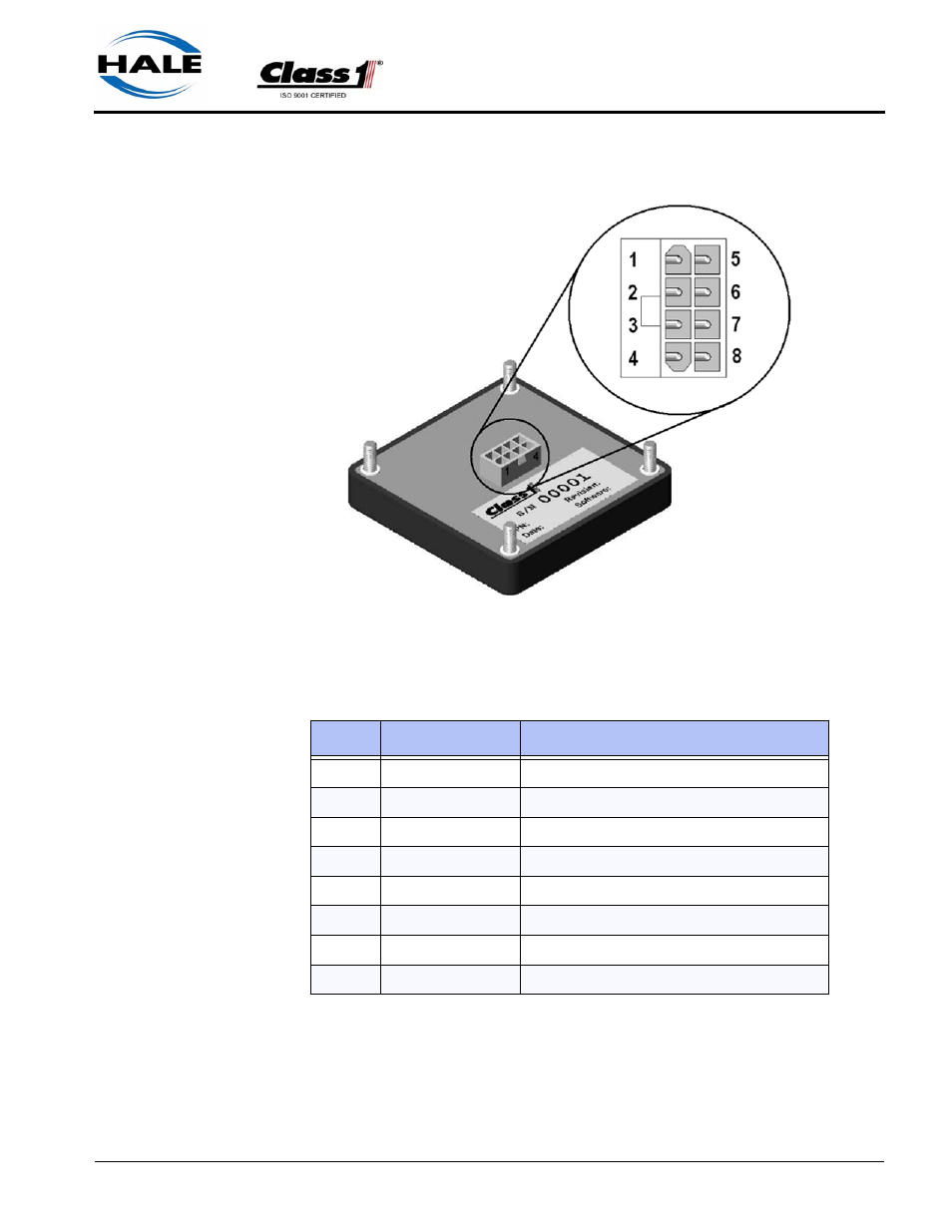
SPC SMART-SWITCH CONTROLLER
Figure 6-3: SPC Connector Arrangement
Pin No.
Circuit
Description
1
(S+) Supply +
Module Supply (+9VDC....+32VDC
2
(CH) CAN High
ES - Key Communications (J1939 CAN)
3
(CL) CAN Low
ES - Key Communications (J1939 CAN)
4
(O +) Output
Electric Valve Control (Positive, 500mA)
5
(I -) Input
Tank Level Switch Input (Ground Polarity)
6
(O +) Output
Tank Select Control (Positive 500mA)
7
(O +) Output
Foam Fill Pump Control (Positive, 500mA)
8
(S -) Supply
Module Supply (Vehicle Ground)
Table 6-4: SPC Connector Assignments
See also other documents in the category Class1 For the car:
- 4 output tank level (5 pages)
- Digital Aerial Warning Display (6 pages)
- Digital Air Minder (8 pages)
- Digital Clock (1 page)
- Digital Display (35 pages)
- Flowminder 102046 - SSD Digital Flow Meter (9 pages)
- Digital Oxygen Remaining (6 pages)
- Digital Pressure Gauge (6 pages)
- Digital Tank Level Display (5 pages)
- Electrical System Manager (15 pages)
- Electronic Fire Commander (8 pages)
- ENFO III (4 pages)
- ENFO IV - 1 page (1 page)
- ENFO IV (10 pages)
- Engine status center (9 pages)
- Engine status OEM menu (3 pages)
- ES-Key-USM (30 pages)
- ESM3 (14 pages)
- Intelli Tank 4 light driver module (9 pages)
- Intelli Tank level display with drip empty (16 pages)
- Intelli-Tank (15 pages)
- Total System Manager (12 pages)
- Total System Manager (19 pages)
- Vernier Throttle for CAT- new (8 pages)
- Vernier Throttle for CAT (12 pages)
- Vernier Throttle for Cummins (9 pages)
- Digital Pressure Service & Calibration (5 pages)
- 109395 - ITL 4LT with 1-wire COM 106296 106299 - 1page (1 page)
- Throttle Information Reference (24 pages)
- ITL Tank Level Driver Module 107451 (9 pages)
- ITL Mini Remote Driver one-page_manual 112648 (1 page)
- Throttle Interface CAT 105216 (8 pages)
- Pump Throttle Electric Cotnrol Series 2 (14 pages)
- 107490 - UNI-Governor 107396 107269 software v 6 00 (38 pages)
- FoamLogix 2.1A & 1.7AHP REV E (96 pages)
- Digital speedometer (4 pages)
- 106759 - ITL 4LT with 1-wire COM 106296 106299 (18 pages)
- 114356 - ITL 4LT with 1-wire and CAN COM 113739 114378 (24 pages)
- 115355 - ITL 4LT with 1-wire and CAN COM 113739 114378 - Page (1 page)
- 117155 - TPG Governor - 117684 EXTERNAL (30 pages)
- 117155 - TPG Governor - 117685 (2 pages)
- 118253 - ITL40 108404-XX - Full (26 pages)
- 118252 - ITL40 118404-XX - Quick Start (1 page)
- 118712 - TPG+ Governor - 118710 (2 pages)