Figure 11, Optional, Figure 12 – Brocade Communications Systems Brocade ICX 6650 53-1002599-01 User Manual
Page 32
16
Brocade ICX 6650 Hardware Installation Guide
53-1002599-01
Installing the device in a rack or cabinet
2
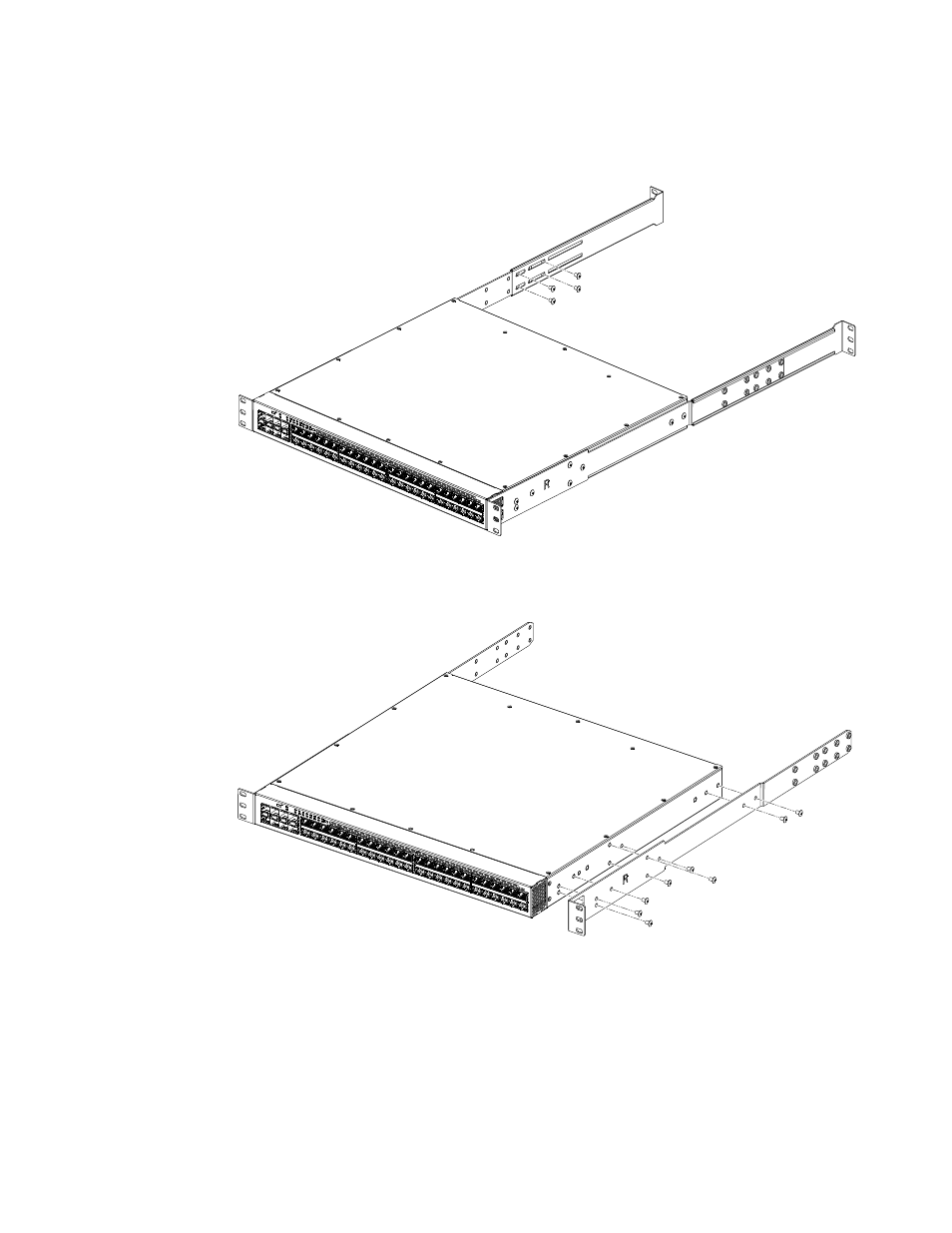
FIGURE 11
Optional 4-post Rack Mount Kit, Rear Attach
FIGURE 12
Optional 4-post Rack Mount Kit, Side Attach
3. Position the switch in the cabinet, providing temporary support under the switch until the rail
kit is secured to the cabinet.
4. Attach the front right bracket to the rail rack using two 10-32 x 5/8 in. screws and the
appropriate round or square retainer nuts.
5. Repeat
to attach the left front bracket to the left front rack rail and tighten all 10-32 x
5/8 in. screws to a torque of 25 in-lb (29 cm-kg). See
.