Bryant 582A User Manual
Page 9
7. Pressure-test all gas piping in accordance with local and
national plumbing and gas codes before connecting piping
to unit.
NOTE:
Pressure test the gas supply system after the gas supply
piping is connected to the gas valve. The supply piping must be
disconnected from the gas valve during the testing of the piping
systems when test pressure is in excess of 0.5 psig. Pressure test
the gas supply piping system at pressures equal to or less than 0.5
psig. The unit heating section must be isolated from the gas piping
system by closing the external main manual shutoff valve and
slightly opening the ground-joint union.
CAUTION:
Unstable operation may occur when the gas
valve and manifold assembly are forced out of position
while connecting improperly-routed rigid gas piping to
the gas valve. Use a backup wrench when making
connection to avoid strain on, or distortion of, the gas
control piping.
CAUTION:
If a flexible conductor is required or al-
lowed by the authority having jurisdiction, black iron
pipe shall be installed at the gas valve and shall extend a
minimum of 2 in. outside the unit casing.
WARNING:
Never use a match or other open flame
when checking for gas leaks. Never purge gas line into
combustion chamber. Failure to follow this warning
could result in an explosion causing serious injury or
death.
TABLE 2—PHYSICAL DATA—UNIT 583A
UNIT SIZE 583A
024040
024060
030040
030060
036060
036090
042060
042090
NOMINAL CAPACITY (ton)
2
2
2½
2½
3
3
3½
3½
OPERATING WEIGHT (lb.)
290
290
313
313
321
321
382
382
COMPRESSORS
Quantity
Scroll
1
REFRIGERANT (R-22)
Quantity (lb.)
3.7
3.7
4.4
4.4
5.2
5.2
6.4
6.4
REFRIGERANT METERING DEVICE
Orifice ID (in.)
.034
.034
.030
.030
.032
.032
.034
.034
CONDENSER COIL
Rows...Fins/in.
Face Area (sq ft)
1...17
10.8
1...17
10.8
1...17
12.7
1...17
12.7
2...17
9.1
2...17
9.1
2...17
12.3
2...17
12.3
CONDENSER FAN
Nominal Cfm
Diameter (in.)
Motor Hp (Rpm)
2350
22
1/8 (825)
2350
22
1/8 (825)
2350
22
1/8 (825)
2350
22
1/8 (825)
2350
22
1/8 (825)
2350
22
1/8 (825)
3300
22
1/8 (825)
3300
22
1/8 (825)
EVAPORATOR COIL
Rows...Fins/in.
Face Area (sq ft)
3...15
3.1
3...15
3.1
3...15
3.1
3...15
3.1
3...15
3.7
3...15
3.7
3...15
4.7
3...15
4.7
EVAPORATOR BLOWER
Nominal Airflow (Cfm)
Size (in.)
Motor Hp (Rpm)
800
10 X 10
1/4 (1075)
800
10 X 10
1/4 (1075)
1000
10 X 10
1/4 (1075)
1000
10 X 10
1/4 (1075)
1200
11 X 10
1/2 (1075)
1200
11 X 10
1/2 (1075)
1400
11 X 10
3/4 (1075)
1400
11 X 10
3/4 (1075)
FURNACE SECTION*
Burner Orifice No. (Qty...Drill Size)
Natural Gas
Burner Orifice No. (Qty...Drill Size)
Propane Gas
2...44
2...50
2...38
2...46
2...44
2...50
2...38
2...46
2...38
2...46
3...38
3...46
2...38
2...46
3...38
3...46
RETURN-AIR FILTERS (in.)†
Throwaway
20 X 20
20 X 20
20 X 20
20 X 20
20 X 24
20 X 24
24 X 30
24 X 30
* Based on altitude of 0 to 2000 ft.
† Required filter sizes shown are based on the larger of the ARI (Air Conditioning and Refrigeration Institute) rated cooling airflow or the heating airflow velocity of 300
ft/minute for high-capacity type. Air filter pressure drop for non-standard filters must not exceed 0.08 in. wg.
Fig. 8—Condensate Trap
C00009
TRAP
OUTLET
2" min.
1" min.
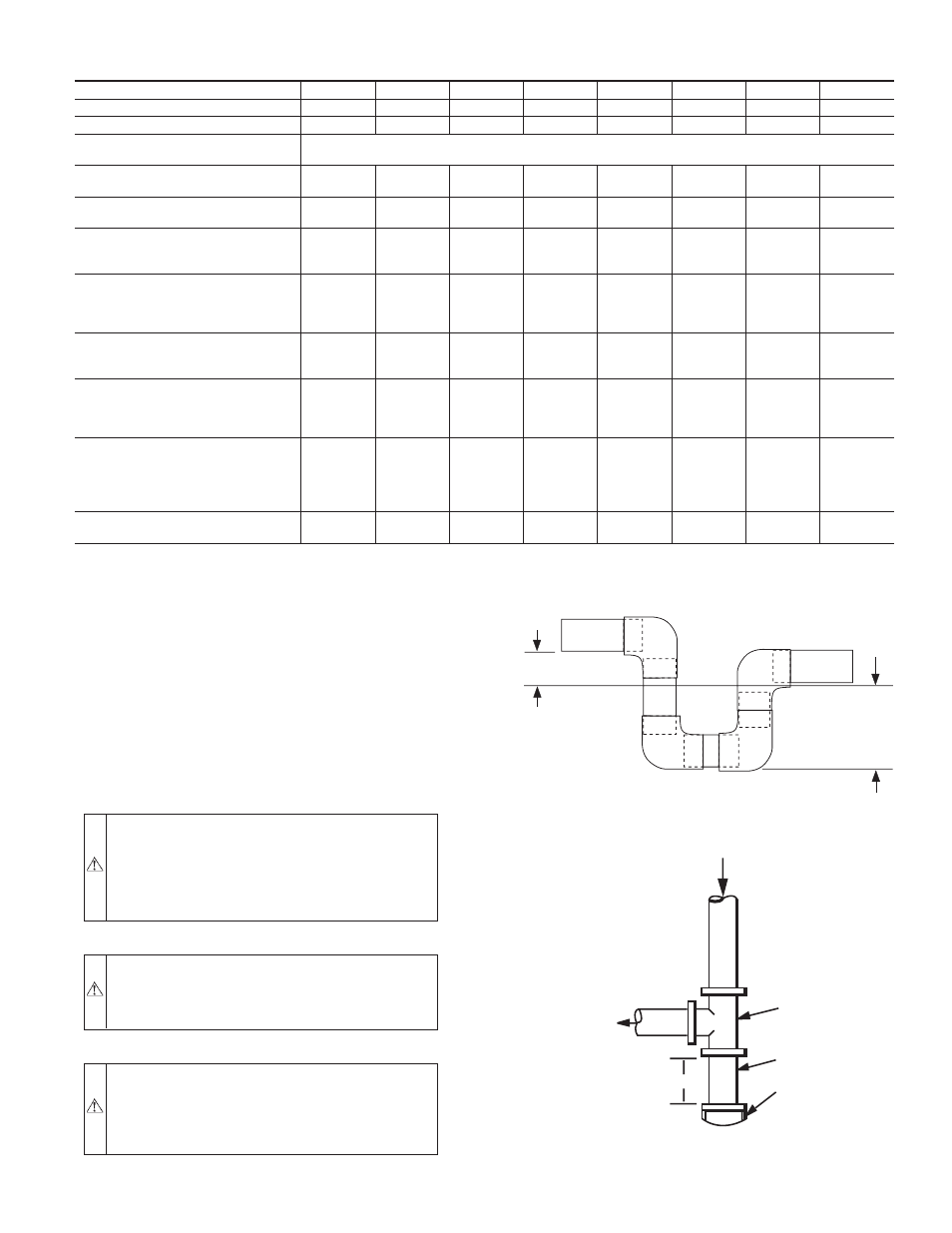
Fig. 9—Sediment Trap
C99020
OUT
TEE
NIPPLE
CAP
IN
3˝ MIN
—9—