Bryant 582A User Manual
Page 7
CAUTION:
Do not restrict condenser airflow. An air
restriction at either the outdoor-air inlet or the fan
discharge can be detrimental to compressor life.
The condenser fan pulls air through the condenser coil and
discharges it through the top cover. Be sure that the fan discharge
does not recirculate to the condenser coil. Do not locate the unit in
either a corner or under an overhead obstruction. The minimum
clearance under a partial overhang (such as a normal house
overhang) is 48-in. above the unit top. The maximum horizontal
extension of a partial overhang must not exceed 48-in..
Do not place the unit where water, ice, or snow from an overhang
or roof will damage or flood the unit. Do not install the unit on
carpeting, tile, or other combustible materials. The unit may be
installed on wood flooring or on Class A, B, or C roof covering
materials.
V.
RIG AND PLACE UNIT
CAUTION:
When installing the unit on a rooftop, be
sure the roof will support the additional weight.
Use spreader bars or crate top when rigging the unit. The units
must be rigged for lifting (See Fig. 6). Refer to Table 1 and 2 for
operating weight. Use extreme caution to prevent damage when
moving the unit. Unit must remain in an upright position during all
rigging and moving operations.The unit must be level within 1/4”
for proper condensate drainage; therefore, the ground-level pad or
accessory roof curb must be level before setting the unit in place.
When a field-fabricated support is used, be sure that the support is
level and properly supports the unit. Lifting point should be
directly over the center of gravity for the unit.
VI.
CONNECT CONDENSATE DRAIN
NOTE:
When installing condensate drain connection be sure to
comply with local codes and restrictions.
Models 582A and 583A dispose of condensate water through a 3/4
in. NPT fitting which exits through the compressor access panel
(See Fig. 2 and 3 for location).
Condensate water can be drained directly onto the roof in rooftop
installations (where permitted) or onto a gravel apron in ground-
level installations. Install a field-supplied condensate trap at end of
condensate connection to ensure proper drainage. Make sure that
the outlet of the trap is at least 1 in. lower than the drain pan
condensate connection to prevent the pan from overflowing (See
Fig. 8). Prime the trap with water. When using a gravel apron,
make sure it slopes away from the unit.
If the installation requires draining the condensate water away
from the unit, install a 2-in. trap at the condensate connection to
ensure proper drainage (See Fig. 8). Make sure that the outlet of
the trap is at least 1 in. lower than the drainpan condensate
connection. This prevents the pan from overflowing.
Prime the trap with water. Connect a drain tube – using a minimum
of 3/4-in. PVC or 3/4-in. copper pipe (all field-supplied) – at the
outlet end of the 2-in. trap. Do not undersize the tube. Pitch the
drain tube downward at a slope of at least 1-in. for every 10 ft of
horizontal run. Be sure to check the drain tube for leaks.
VII.
INSTALL FLUE HOOD
The flue hood assembly is shipped screwed to the coil panel in the
indoor blower compartment. Remove the service access panel to
locate the assembly (See Fig. 31).
NOTE:
Dedicated low NO
x
models MUST be installed in Cali-
fornia Air Quality Management Districts where a Low NO
x
rule
exists.
These models meet the California maximum oxides of nitrogen
(NO
x
) emissions requirements of 40 nanograms/joule or less as
shipped from the factory.
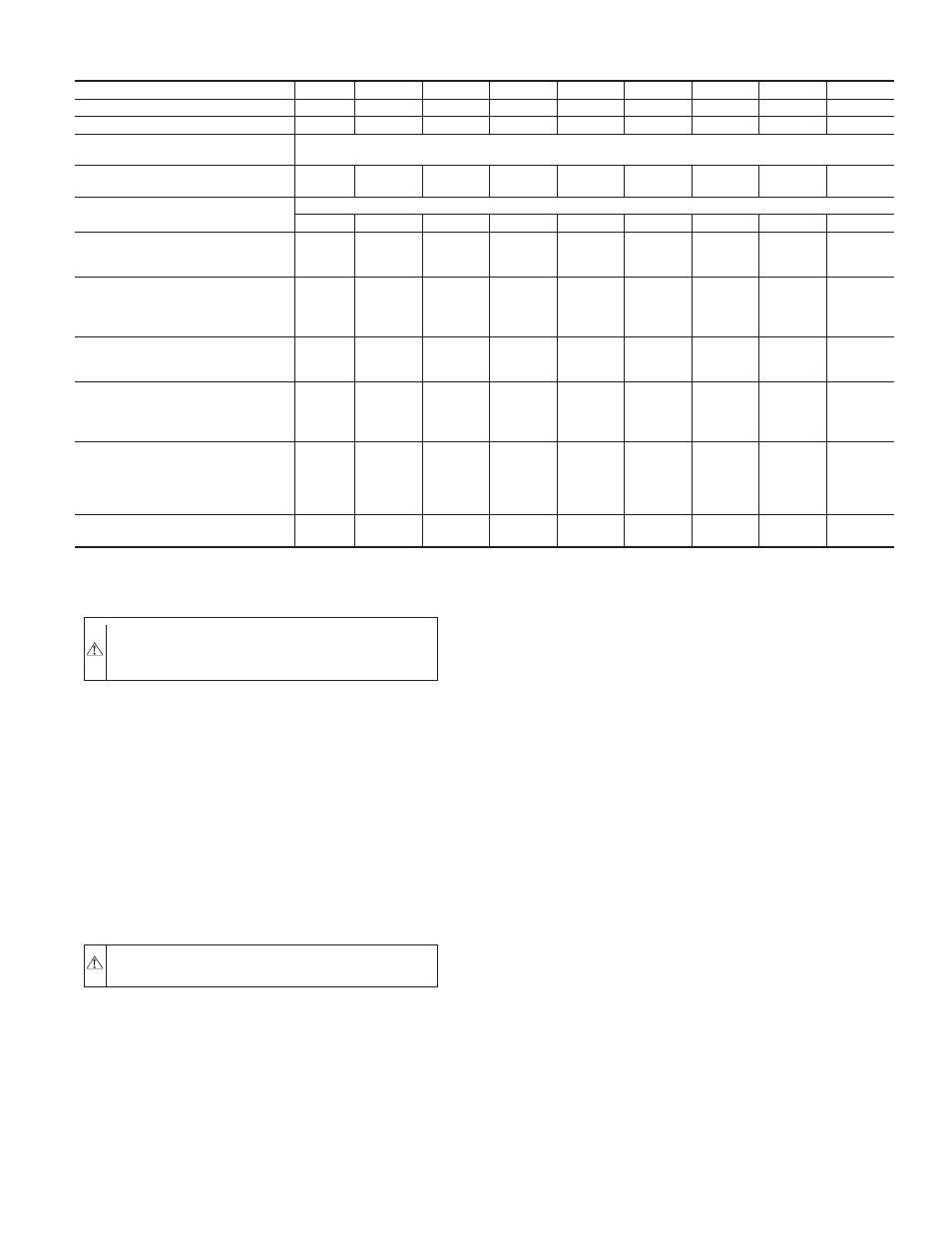
TABLE 1—PHYSICAL DATA—UNIT 582A
UNIT SIZE 582A
018040
024040
024060
030040
030060
036060
036090
042060
042090
NOMINAL CAPACITY (ton)
1½
2
2
2½
2½
3
3
3½
3½
OPERATING WEIGHT (lb.)
249
280
280
280
280
320
320
355
355
COMPRESSORS
Quantity
Reciprocating
1
REFRIGERANT (R-22)
Quantity (lb.)
2.6
3.5
3.5
3.65
3.65
4.4
4.4
5.7
5.7
REFRIGERANT METERING DEVICE
Orifice ID (in.)
Acutrol™ Device
.034
.034
.034
.034
.034
.032
.032
.034
.034
CONDENSER COIL
Rows...Fins/in.
Face Area (sq ft)
1...17
6.1
1...17
9.1
1...17
9.1
1...17
9.1
1...17
9.1
1...17
10.9
1...17
10.9
1...17
9.1
1...17
9.1
CONDENSER FAN
Nominal Cfm
Diameter (in.)
Motor Hp (Rpm)
2000
22
1/8 (825)
2400
22
1/8 (825)
2400
22
1/8 (825)
2400
22
1/8 (825)
2400
22
1/8 (825)
3000
22
¼ (1100)
3000
22
¼ (1100)
3000
22
¼ (1100)
3000
22
¼ (1100)
EVAPORATOR COIL
Rows...Fins/in.
Face Area (sq ft)
2...15
3.1
2...15
3.1
2...15
3.1
2...15
3.1
2...15
3.1
3...15
3.1
3...15
3.1
4...15
3.1
4...15
3.1
EVAPORATOR BLOWER
Nominal Airflow (Cfm)
Size (in.)
Motor HP (Rpm)
600
10 x 10
1/4 (875)
800
10 x 10
1/4 (1075)
800
10 x 10
1/4 (1075)
1000
10 x 10
1/4 (1075)
1000
10 x 10
1/4 (1075)
1200
11 x 10
1/2 (1075)
1200
11 x 10
1/2 (1075)
1400
11 x 10
3/4 (1075)
1400
11 x 10
3/4 (1075)
FURNACE SECTION*
Burner Orifice No. (Qty...Drill Size)
Natural Gas
Burner Orifice No. (Qty...Drill Size)
Propane Gas
2...45
2...50
2...45
2...50
2...38
2...46
2...45
2...50
2...38
2...46
2...38
2...46
3...38
3...46
2...38
2...46
3...38
3...46
RETURN-AIR FILTERS (in.)†
Throwaway
20 x 20
20 x 20
20 X 20
20 x 20
20 X 20
20 X 24
20 X 24
20 x 24
20 x 24
* Based on altitude of 0 to 2000 ft.
† Required filter sizes shown are based on the larger of the ARI (Air Conditioning and Refrigeration Institute) rated cooling airflow or the heating airflow velocity of 300
ft/minute for throwaway type or 450 ft/minute for high-capacity type. Air filter pressure drop for non-standard filters must not exceed 0.08 in. wg.
—7—