Bryant 582A User Manual
Page 11
6. Cover both horizontal duct openings with the duct covers
from the accessory duct cover kit. Ensure opening is air-
and watertight.
7. After completing unit conversion, perform all safety checks
and power up unit.
NOTE:
The design and installation of the duct system must be in
accordance with the standards of the NFPA for installation of
nonresidence-type air conditioning and ventilating systems, NFPA
90A or residence-type, NFPA 90B; and/or local codes and
ordinances.
Adhere to the following criteria when selecting, sizing, and
installing the duct system:
1. Units are shipped for horizontal duct installation (by remov-
ing duct covers).
2. Select and size ductwork, supply-air registers, and return-air
grilles according to American Society of Heating, Refrig-
eration and Air Conditioning Engineers (ASHRAE) recom-
mendations.
3. Use flexible transition between rigid ductwork and unit to
prevent transmission of vibration. The transition may be
screwed or bolted to duct flanges. Use suitable gaskets to
ensure weathertight and airtight seal.
4. All units must have field-supplied filters or accessory filter
rack installed in the return-air side of the unit. Recom-
mended sizes for filters are shown in Tables 1 and 2.
5. Size all ductwork for maximum required airflow (either
heating or cooling) for unit being installed. Avoid abrupt
duct size increases or decreases or performance may be
affected.
6. Adequately insulate and weatherproof all ductwork located
outdoors. Insulate ducts passing through unconditioned
space, and use vapor barrier in accordance with latest issue
of Sheet Metal and Air Conditioning Contractors National
Association (SMACNA) and Air Conditioning Contractors
of America (ACCA) minimum installation standards for
heating and air conditioning systems. Secure all ducts to
building structure.
7. Flash, weatherproof, and vibration-isolate all openings in
building structure in accordance with local codes and good
building practices.
X.
INSTALL ELECTRICAL CONNECTIONS
WARNING:
The unit cabinet must have an uninter-
rupted, unbroken electrical ground to minimize the pos-
sibility of serious injury if an electrical fault should occur.
This ground may consist of an electrical wire connected
to the unit ground lug in the control compartment, or
conduit approved for electrical ground when installed in
accordance
with
NEC
(National
Electrical
Code)
ANSI/NFPA (latest edition) and local electrical codes. In
Canada, follow Canadian Electrical Code CSA (Canadian
Standards Association) C22.1 and local electrical codes.
Failure to adhere to this warning could result in serious
injury or death.
CAUTION:
Failure to follow these precautions could
result in damage to the unit being installed:
1. Make all electrical connections in accordance with
NEC ANSI/NFPA (latest edition) and local electrical
codes governing such wiring. In Canada, all electrical
connections must be in accordance with CSA standard
C22.1 Canadian Electrical Code Part 1 and applicable
local codes. Refer to unit wiring diagram.
2. Use only copper conductor for connections between
field-supplied electrical disconnect switch and unit.
DO NOT USE ALUMINUM WIRE.
3. Be sure that high-voltage power to unit is within
operating voltage range indicated on unit rating plate.
4. Do not damage internal components when drilling
through any panel to mount electrical hardware, con-
duit, etc. On 3-phase units, ensure phases are balanced
within 2 percent. Consult local power company for
correction of improper voltage and/or phase imbal-
ance.
A.
HIGH-VOLTAGE CONNECTIONS
The unit must have a separate electrical service with a field-
supplied, waterproof, disconnect switch mounted at, or within
sight from, the unit. Refer to the unit rating plate for maximum
fuse/circuit breaker size and minimum circuit amps (ampacity) for
wire sizing (See Tables 4 and 5 for electrical data).
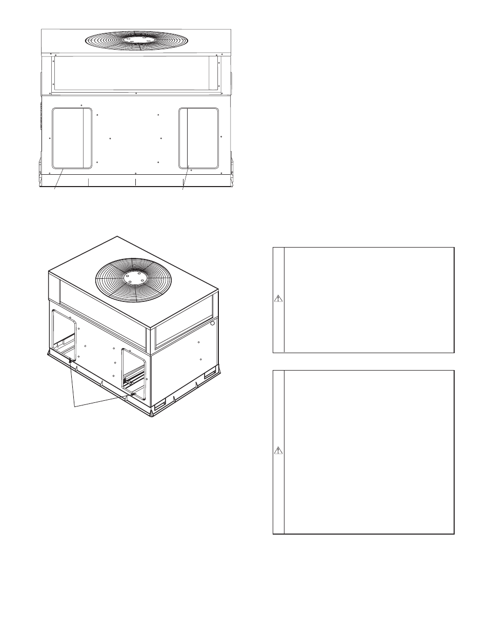
Fig. 10A Supply and Return Duct Opening
C99011
SUPPLY
DUCT
OPENING
RETURN
DUCT
OPENING
Fig. 10B—Vertical Duct Cover Removed
C99012
DUCT COVERS REMOVED
—11—