Bryant 582A User Manual
Page 20
When the air temperature at the limit switch drops to the
low-temperature setting of the limit switch, the switch closes and
completes the R control circuit. The electric-spark ignition system
cycles and the unit returns to normal heating operation.
H.
AUXILIARY LIMIT SWITCH (ROLLOUT)
The function of the switch is to close the main gas valve in the
event of flame rollout. The switch is located above the main
burners. When the temperature at the auxiliary switch reaches the
maximum allowable temperature, the R control circuit trips,
closing the gas valve and stopping gas flow to the burners. The
indoor (evaporator) fan motor (IFM) and induced draft motor
continue to run until switch is reset. The IGC LED will display
FAULT CODE 7.
III.
START-UP COOLING AND MAKE ADJUSTMENTS
CAUTION:
Complete the required procedures given in
the Pre-Start-Up section before starting the unit.
Do not jumper any safety devices when operating the
unit.
Do not operate the compressor when the outdoor tem-
perature is below 40°F (unless accessory low-ambient kit
is installed).
Do not rapid-cycle the compressor. Allow 5 minutes
between ‘‘on’’ cycles to prevent compressor damage.
A.
CHECKING COOLING CONTROL OPERATION
Start and check the unit for proper cooling control operation as
follows:
1. Place room thermostat SYSTEM switch in OFF position.
Observe that blower motor starts when FAN switch is
placed in ON position and shuts down when FAN switch is
placed in AUTO. position.
2. Place SYSTEM switch in COOL position and FAN switch
in AUTO. position. Set cooling control below room tem-
perature. Observe that compressor, condenser fan, and
evaporator blower motors start. Observe that cooling cycle
shuts down when control setting is satisfied. The evaporator
fan will continue to run for 30 sec.
3. When using an auto-changeover room thermostat, place
both SYSTEM and FAN switches in AUTO. positions.
Observe that unit operates in Heating mode when tempera-
ture control is set to ‘‘call for heating’’ (above room
temperature) and operates in Cooling mode when tempera-
ture control is set to ‘‘call for cooling’’ (below room
temperature).
IMPORTANT: Three-phase, scroll compressor units
(582A048 and 583A030-060) are direction-oriented. These
units must be checked to ensure proper compressor 3-phase
power lead orientation. If not corrected within 5 minutes,
the internal protector shuts off the compressor. The 3-phase
power leads to the unit must be reversed to correct rotation.
When turning backwards, scroll compressors emit elevated
noise levels, and the difference between compressor suction
and discharge pressures may be dramatically lower than
normal.
B.
CHECKING
AND
ADJUSTING
REFRIGERANT
CHARGE
The refrigerant system is fully charged with R-22 refrigerant,
tested, and factory-sealed.
NOTE:
Adjustment of the refrigerant charge is not required
unless the unit is suspected of not having the proper R-22 charge.
A superheat charging chart is attached to the outside of the service
access panel. The chart includes the required suction line tempera-
ture at given suction line pressures and outdoor ambient tempera-
tures.
An accurate superheat, thermocouple- or thermistor-type ther-
mometer, a sling psychrometer, and a gauge manifold are required
when using the superheat charging method for evaluating the unit
charge. Do not use mercury or small dial-type thermometers
because they are not adequate for this type of measurement.
CAUTION:
When evaluating the refrigerant charge, an
indicated adjustment to the specified factory charge must
always be very minimal. If a substantial adjustment is
indicated, an abnormal condition exists somewhere in the
cooling system, such as insufficient airflow across either
coil or both coils.
Proceed as follows:
1. Remove caps from low- and high-pressure service fittings.
2. Using hoses with valve core depressors, attach low- and
high-pressure gauge hoses to low- and high-pressure service
fittings, respectively.
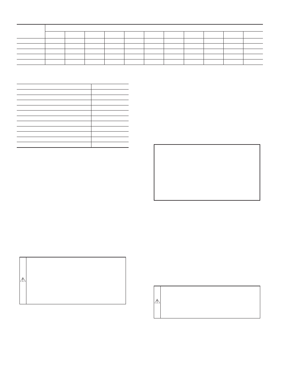
TABLE 7—AIR DELIVERY (CFM) AT INDICATED TEMPERATURE RISE AND RATED HEATING INPUT
HEATING
INPUT
(BTUH)
TEMPERATURE RISE °F
20
25
30
35
40
45
50
55
60
65
70
40,000
1500
1200
1000
857
750
667
600
545
500
—
—
60,000
2250
1800
1500
1286
1125
1000
900
818
750
692
—
90,000
—
—
2250
1929
1688
1500
1350
1227
1125
1038
964
115,000
—
—
—
2464
2156
1917
1725
1568
1438
1327
1232
130,000
—
—
—
2786
2438
2167
1950
1773
1625
1500
—
NOTE: Dashed areas do not fall within the approved temperature rise range of the unit.
TABLE 8—LED INDICATIONS
ERROR CODE
LED INDICATION
Normal Operation
On
Hardware Failure
Off
Fan On/Off Delay Modified
1 Flash
Limit Switch Fault
2 Flashes
Flame Sense Fault
3 Flashes
Four Consecutive Limit Switch Faults
4 Flashes
Ignition Lockout Fault
5 Flashes
Induced-Draft Motor Fault
6 Flashes
Rollout Switch Fault
7 Flashes
Internal Control Fault
8 Flashes
Temporary lock-out (1 hr)
9 Flashes
NOTES:
1. There is a 3-sec. pause between error code displays.
2. If more than one error code exists, all applicable error codes will be
displayed in numerical sequence
3. This chart is on the wiring diagram located inside the burner access panel.
—20—