Bryant 582A User Manual
Page 14
Immediately upon detection of gas odor,
retighten the union. Allow 5 minutes to
elapse, then light unit.
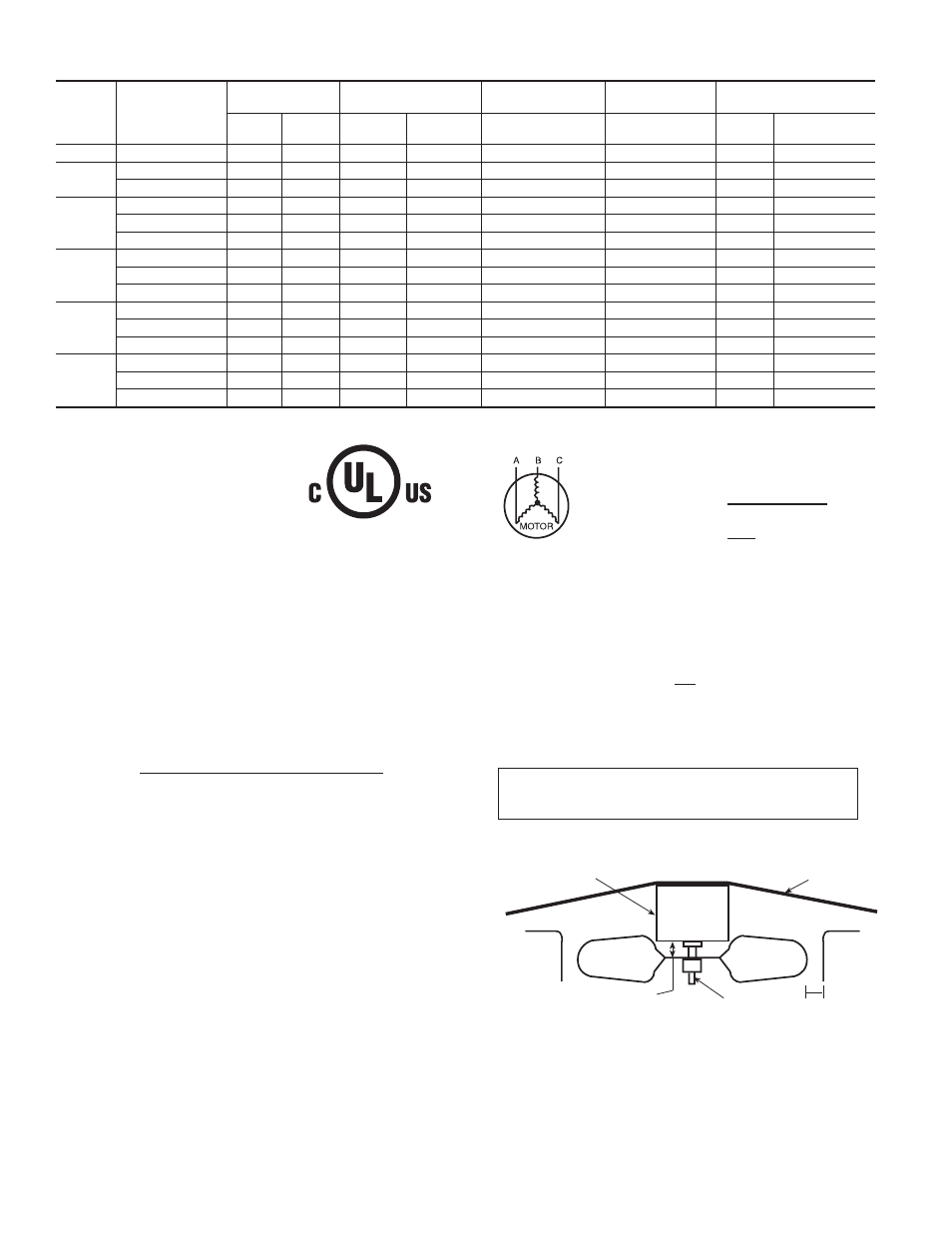
b. Make sure that condenser-fan blade is correctly posi-
tioned in fan orifice. Leading edge of condenser-fan
blade should be 1/2 in. maximum from fan orifice
venturi.
c. Ensure fan hub is 1/8 in. maximum from motor housing
(See Fig. 12).
d. Make sure that air filter(s) is in place.
e. Make sure that condensate drain trap is filled with water
to ensure proper drainage.
f. Make sure that all tools and miscellaneous loose parts
have been removed.
START-UP
I.
CHECK FOR REFRIGERANT LEAKS
Proceed as follows to locate and repair a refrigerant leak and to
charge the unit:
1. Locate leak and make sure that refrigerant system pressure
has been relieved and reclaimed from both high- and
low-pressure ports.
TABLE 5—ELECTRICAL DATA—UNIT 583A
UNIT
SIZE
583A
V-PH-HZ
VOLTAGE
RANGE
COMPRESSOR
OUTDOOR FAN
MOTOR
INDOOR FAN
MOTOR
POWER SUPPLY
Min
Max
RLA
LRA
FLA
FLA
MCA
Max Fuse or
Ckt Bkr
024
208/230–1–60
187
253
10.9
54.0
0.9
2.0
16.5
25
030
208/230–1–60
187
253
13.5
73.0
0.8
2.1
19.8
30
208/230–3–60
187
253
9.0
63.0
0.8
2.1
14.2
20
036
208/230–1–60
187
253
16.7
97.0
0.8
3.6
25.3
40
208/230–3–60
187
253
11.2
75.0
0.8
3.6
18.4
25
460–3–60
414
506
5.4
37.5
0.9
1.9
9.6
15
042
208/230–1–60
187
253
17.9
104.0
1.6
4.1
28.1
45
208/230–3–60
187
253
12.4
88.0
1.6
4.1
21.2
30
460–3–60
414
506
6.1
44.0
0.9
2.0
10.5
15
048
208/230–1–60
187
253
23.4
126.0
1.5
4.1
34.9
4
5
208/230–3–60
187
253
13.0
93.0
1.5
4.1
21.9
30
460–3–60
414
506
6.4
46.5
0.9
1.9
10.8
15
060
208/230–1–60
187
253
28.8
169.0
1.6
6.2
43.8
60
208/230–3–60
187
253
17.3
123.0
1.6
6.2
29.4
45
460–3–60
414
506
9.0
62.0
0.9
3.2
15.4
20
Table 5—Legend
C99024
452 = 5 v
457 = 7 v
455 = 2 v
LEGEND
FLA
— Full Load Amps
LRA
— Locked Rotor Amps
MCA
— Minimum Circuit Amps
MOCP — Maximum Overcurrent Protection
RLA
— Rated Load Amps
NOTES:
1. In compliance with NEC (National Electrical Code) requirements
for multimotor and combination load equipment (refer to NEC
Articles 430 and 440), the overcurrent protective device for the
unit shall be Power Supply fuse . Canadian units may be
fuse or circuit breaker.
2. Minimum wire size is based on 60 C copper wire. If other than
60 C wire is used, or if length exceeds wire length in table,
determine size from NEC.
3. Unbalanced 3-Phase Supply Voltage
Never operate a motor where a phase imbalance in supply volt-
age is greater than 2%. Use the following formula to determine
the percentage of voltage imbalance.
% Voltage imbalance
max voltage deviation from average voltage
= 100 x
average voltage
EXAMPLE: Supply voltage is 460-3-60.
AB = 452 v
BC = 464 v
AC = 455 v
452 + 464 + 455
Average Voltage =
3
1371
=
3
= 457
Determine maximum deviation from average voltage.
(AB) 457
(BC) 464
(AC) 457
Maximum deviation is 7 v.
Determine percent of voltage imbalance.
7
% Voltage Imbalance = 100 x
457
= 1.53%
This amount of phase imbalance is satisfactory as it is below the
maximum allowable 2%.
IMPORTANT: If the supply voltage phase imbalance is
more than 2%, contact your local electric utility company
immediately.
®
CKT BKR — Circuit Breaker
Fig. 12—Fan Blade Clearance
C99009
FAN GRILLE
MOTOR
1/8" MAX BETWEEN
MOTOR AND FAN HUB
MOTOR SHAFT
1/2˝
—14—