Baffle assembly, Support – Bryant R-22 User Manual
Page 5
Calculate the linear length of vapor tube required, adding any
losses for the total number of elbows for application. (See Table
5.) Using this equivalent length, select desired vapor-line size from
Table 4. Subtract the nominal percentage loss from outdoor-unit
presale-literature Detailed Cooling Capacities data for the given
indoor/outdoor combination. Reference all notes of Table 4.
NOTE:
When specifying vapor-line insulation, be aware of the
following standard practice:
All standard accessory-tubing kits are supplied with 3/8-in. insu-
lation on vapor line.
For minimal capacity loss in long-line application, 1/2-in. insula-
tion should be specified.
TABLE 2—WIND BAFFLE DIMENSIONS FOR RELIANT UNITS WITH AEROQUIET-SYSTEM TOP (IN.)
UNIT SIZE
AA
UNIT HEIGHT
A
B
C
D
E
F
G
H
J
K
L
Small
26-3/16
23-13/16
17-1/4
24-5/16
10-1/4
19-3/4
20-1/2
34-1/2
19-5/8
20-3/8
19-5/8
0
0
27-13/16
17-1/4
24-5/16
10-1/4
23-3/4
24-1/2
34-1/2
23-5/8
24-3/8
23-5/8
0
11-7/8
33-13/16
17-1/4
24-5/16
10-1/4
29-3/4
30-1/2
34-1/2
29-5/8
30-3/8
29-5/8
0
14-7/8
Medium
33
27-13/16
21
30-5/8
10-1/4
23-3/4
24-1/2
42
23-5/8
24-3/8
23-5/8
17-1/8
11-7/8
33-13/16
21
30-5/8
10-1/4
29-3/4
30-1/2
42
29-5/8
30-3/8
29-5/8
17-1/8
14-7/8
39-13/16
21
30-5/8
10-1/4
35-3/4
36-1/2
42
35-5/8
36-3/8
35-5/8
17-1/8
17-7/8
Large
42-1/16
33-13/16
25-5/16
39-3/4
10-1/4
29-3/4
30-1/2
50-9/16
29-5/8
30-3/8
29-5/8
21-11/16
14-7/8
39-13/16
25-5/16
39-3/4
10-1/4
35-3/4
36-1/2
50-9/16
35-5/8
36-3/8
35-5/8
21-11/16
17-7/8
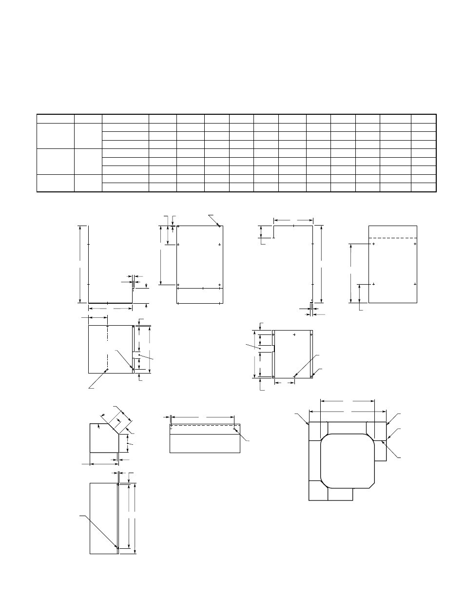
Fig. 2—Wind Baffle Construction for Cube Units
A95446
LEFT
SIDE
RIGHT
SIDE
SCREW
14 REQ'D
SUPPORT
3 REQ'D
OUTDOOR
UNIT
BAFFLE ASSEMBLY
1
/
4
″
x
3
/
8
″
(5.56 x 9.53) SLOT
6 REQ'D
13
/
64
″
(5.4)
TYP
SUPPORT
MAT'L: 18 GA STEEL
1
/
2
″
(12.7)
1
/
4
″
(6.4)
B
C
5
3
/
64
″
(128.0)
7
7
/
8
″
(199.9)
D
A
2
1
/
2
″
(63.5)
1
21
/
32
″
(42.1)
1
/
4
″
x
3
/
8
″
(5.56 x 9.53) SLOT
6 REQ'D
1
/
4
″
(5.56) DIA
2 REQ'D
25
/
64
″
(10.0)
E
7
7
/
8
″
(200.0)
3
/
16
″
(4.6)
1
/
8
″
(3.45) DIA
2 REQ'D
BAFFLE - LEFT
MAT'L: 20 GA STEEL
F
C
5
3
/
64
″
(128.0)
1
/
2
″
(12.7)
TYP
E
7
29
/
32
″
(200.8)
BAFFLE - RIGHT
MAT'L: 20 GA STEEL
A
D
1
21
/
32
″
(42.1)
25
⁄
64
″
(10.0)
2
1
/
2
″
(63.5)
G
1
/
4
″
(5.56) DIA
4 REQ'D
J
C
AA
H
J
1
/
4
″
(6.4)
23
/
64
″
(9.2)
1
/
2
″
(12.7)
TYP
8
5
/
64
″
(205.3)
TYP
4
57
⁄
64
″
(124.2) TYP
2
5
/
64
″
(52.6)
4
9
/
64
″
(105.2)
45
°
TYP
1
/
8
″
(3.45) DIA.
4 REQ'D
1
/
4
″
(5.56) DIA
2 REQ'D
23
/
64
″
(9.2)
—5—