Scroll gas flow – Bryant R-22 User Manual
Page 28
5. Scratch matching marks on stubs in old compressor. Make
corresponding marks on replacement compressor.
6. Use torch to remove stubs from old compressor and to
reinstall them in replacement compressor.
7. Use copper couplings to tie compressor back into system.
8. Evacuate system, recharge, and check for normal system
operation.
9. Copeland CR-6 and scroll compressors have copper-plated,
steel-suction ports. Excess heat during brazing will burn off
copper plating. See Brazing section for additional informa-
tion.
COPELAND SCROLL COMPRESSOR
I.
FEATURES
The scroll compressor pumps refrigerant through the system by the
interaction of a stationary and an orbiting scroll. (See Fig. 29.) The
scroll compressor has no dynamic suction or discharge valves, and
it is more tolerant of stresses caused by debris, liquid slugging, and
flooded starts. Due to the design of the scroll compressor, the
internal compression components unload (equalize pressure) on
shutdown. The white oil (Sontex 200LT) used in the scroll is
compatible with 3GS oil, which can be used if additional oil is
required. (See Table 13 for oil recharge requirements.)
II.
TROUBLESHOOTING
Troubleshooting mechanical or electrical problems in a scroll
compressor is the same as for a reciprocating compressor, except
that a scroll compressor should never be allowed to pump into a
vacuum. If a pumpdown procedure is used, the scroll compressor
is capable of pumping into a vacuum very quickly, which could
cause fusite arcing and compressor failure. See Step IV of
Reciprocating Compressor section for removal and replacement.
III.
DISCHARGE THERMOSTAT
Some scroll compressors have a discharge thermostat that recip-
rocating compressors do not have. This thermostat is mounted in a
well in the top of the compressor shell to sense if the discharge
temperature reaches 290°F and shuts down the compressor to
prevent damage to it. When the temperature of the thermostat
reaches 140°F, power is restored to the compressor.
To determine if the thermostat is operating properly, either attach
the thermocouple of an electronic thermometer to the dome of the
compressor near the thermostat, or remove the thermostat and
place the thermocouple inside the well. The electronic thermom-
eter must be capable of reading at least 300°F. Start the unit and let
it run for at least 15 minutes to obtain normal operating conditions.
Watch the thermometer to see if it is approaching 270°F. If the
thermocouple is located on the dome near the discharge thermo-
stat, there could be a 20° difference between well and dome
temperatures. If the temperature approaches 270°F, repair system
problem, such as low charge, blocked condenser coil, and so forth.
If the temperature does not approach 270°F, replace discharge
thermostat.
Replacing Discharge Thermostat
To replace the discharge thermostat, refer to the Installation
Instructions packaged with the replacement discharge thermostat
kit. (See Fig. 30.)
IV.
DISCHARGE SOLENOID VALVE
Some larger units equipped with scroll compressors contain a
solenoid valve that is piped between the discharge tube and suction
tube of the compressor. The purpose of the solenoid valve is to
TABLE 13—COMPRESSOR OIL RECHARGE
COMPRESSOR MODEL
RECHARGE
(FL. OZ.)
OIL TYPE
Carlyle/Scroll
″
J
″
Type
44
Suniso 3GS
SC, SRD450AC
34
Zerol 150
w/3 percent
Syn-O-Ad
SR
52
SRH482, SRY482
68
SRH602, SRY602
70
Copeland
CRG3, CRH3, CRJ3, CRK3, CRL3
51
Suniso 3GS
CRN5, CRP5, CRT5, CTH1, CTL1
66
CRC4, CRZ4
36
CR16K6 THROUGH CR42K6
42
*ZR18K1
19
*ZR23K1, ZR28K1
24
*ZR34K1
30
*ZR40K1
34
*ZR49K1-PFV
56
*ZR49K2-TF5, ZR49K2-TFD
56
*ZR61K2-PFV
56
*ZR61K2-TF5, ZR61K2-TFD
66
Tecumseh
AV55
50
Suniso 3GS
AW55
30
AG
60
Bristol
H23A
52
Suniso 3GS
H23B
37
H24A3, H24A4
47
H24A5
52
H25A, H26A
62
H25B, H26B, H29B
32
*Copeland scrolls are charged initially with Sontex 200LT white oil. Since this
oil is not commercially available, use 3GS.
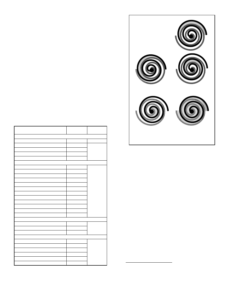
Fig. 29—Scroll Compressor Refrigerant Flow
A90198
Scroll Gas Flow
Compression in the scroll is
created by the interaction of
an orbiting spiral and a
stationary spiral. Gas enters
an outer opening as one of the
spirals orbits.
The open passage is sealed off
as gas is drawn into the spiral.
By the time the gas arrives at
the center port, discharge
pressure has been reached.
Actually, during operation, all
six gas passages are in various
stages of compression at all
times, resulting in nearly con-
tinuous suction and discharge.
As the spiral continues to orbit,
the gas is compressed into an
increasingly smaller pocket.
1
2
3
5
4
—28—