Fig. 33—two-speed control board, Fig. 34—speedup terminals – Bryant R-22 User Manual
Page 31
HEATING OPERATION (HEAT PUMP ONLY)
The 2-speed products utilize a 2-stage-heating indoor thermostat.
The first stage of heating is heat-pump operation (Y1). Auxiliary
backup heat is controlled by second stage (W2). There is a 2°
differential between first and second stage. The control board
determines the compressor speed based on ambient temperature.
See Table 14 for ambient temperatures at which speed changes
occur. When high-speed, heat-pump heating is required, the
control provides a Y2 (24vac) signal back to the thermostat to
energize high-speed-indicator LED.
LED FUNCTION LIGHTS
When using the factory-authorized indoor thermostats with the
2-speed outdoor units, there are 2 locations where system-function
LED-indicator lights are available. The indoor thermostat provides
indicator lights for high- and low-speed operation, system mal-
function, and auxiliary heat for heat pumps. The 2-speed control
board has an LED which provides signals for several system
operations. See Table 15 for LED functions, indicator locations,
and definitions. Table 15 also provides the order of signal
importance if more than 1 signal should occur. The signal to the
indoor thermostat is supplied by the low-voltage
″
L
″
lead.
THREE-SECOND TIME DELAY
Any time the control receives a 24v input, such as Y1 or Y2, there
is a 3-sec time delay before the control function is initiated. This
helps prevent nuisance trips and thermostat
″
jiggling.
″
ONE-MINUTE SPEED-CHANGE TIME DELAY
When the compressor changes speeds from high to low or low to
high, there is a 1-minute time delay before the compressor restarts.
The outdoor fan motor remains running.
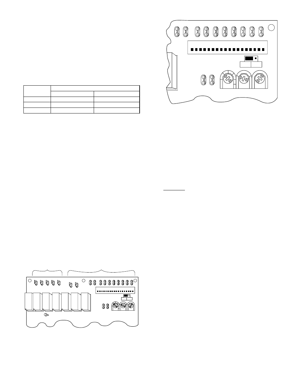
FIVE-MINUTE TIME DELAY
The 2-speed-control logic contains a 5-minute time delay that
prevents the unit from short cycling after a thermostat-off cycle or
power interruption. The unit can be forced to operate immediately
by momentarily touching a jumper between the speed-up terminals
of the control board. (See Fig. 33 and 34.) The speed-up feature
will not bypass any other function or time delay.
TWO-MINUTE LOW-SPEED MINIMUM
If the unit has not operated within the past 30 minutes, the unit
operates for a minimum of 2 minutes in low speed upon the next
thermostat high or low demand.
CRANKCASE-HEATER OPERATION
The 2-speed control energizes the crankcase heater during the
unit’s off cycle when the outdoor ambient is below 75°F.
OUTDOOR FAN-MOTOR OPERATION
The 2-speed control energizes the outdoor fan any time the
compressor is operating. The outdoor fan remains energized during
the 1-minute, speed-change time delay and if a pressure switch or
compressor PTC overload should trip.
If the outdoor fan motor won’t run, check the header-pin housing.
(See Fig. 37.) There should be NO jumper wire between Terminals
15 and 16.
Heat Pumps
After the termination of a defrost cycle, the outdoor fan delays
come on for 20 sec. This allows the refrigeration system to recover
the outdoor coil heat and minimize the
″
steam cloud
″
effect.
SECOND-STAGE LATCHING
When low-speed cooling operation no longer satisfies the first
stage of the indoor thermostat, the indoor temperature will increase
by 2° until second stage is energized. After high-speed cooling
satisfies second stage, it returns to low-speed cooling operation. If
desired, the installer may select to have high-speed cooling by
energizing Y1. High speed will stay energized until Y1 is satisfied.
This eliminates the temperature drop between the first and second
stages of indoor thermostat, holding room temperature closer to set
point.
To utilize this function, the unit capacity should be plotted versus
the heat gain of the structure, which provides the system’s balance
point when the structure requires high-speed capacity. (See Fig.
35.)
Second-stage latching can be selected by rotating the potentiom-
eter (POT) to the desired outdoor second-stage latching tempera-
ture (See Fig. 34.) The temperatures that can be selected are 85°,
90°, 95°, 100°, and 105°F. The POT is factory set at 105°F.
ZONE SELECTION
If the stage–2 latch POT is set to ZONE position, the compressor
operating speed in either heat or cool mode is determined by the
Y1 and/or Y2 inputs. The system operates in low speed with a Y1
input and high speed with Y2 or Y1-and-Y2 input. This allows the
multistage-zoning system to determine what speed is needed
regardless of outdoor temperature or switchover point.
DEFROST TIME SELECTION
The defrost interval can be field selected, depending on local or
geographic requirements. It is factory set at 90 minutes and can be
changed to either 30 or 50 minutes by rotating the defrost-time
POT. (See Fig. 34.)
TABLE 14—AMBIENT TEMPERATURE FOR HIGH- AND
LOW-SPEED OPERATION
UNIT
SIZE
AMBIENT TEMPERATURE (°F)
High Speed
Low Speed
036
30 or less
31 or greater
048
33 or less
34 or greater
060
40 or less
41 or greater
Fig. 33—Two-Speed Control Board
A93569
HIGH VOLTAGE
LOW VOLTAGE
L2
LO
HI
CCH
ODF
O
C
LM1 LM2
DFT1 DFT2 T1
T2
S2
S1
PW2 PW1
P1
1
18
SPEED-UP
STAGE 2
LATCH
DEFROST
TIME
BALANCE
POINT
K7
K6
K5
K4
K3
K2
K1
LED 1
FURN INT
OFF
ON
Fig. 34—Speedup Terminals
A93568
LM1 LM2
DFT1 DFT2 T1
T2
S2
S1
PW2 PW1
P1
1
18
SPEED-UP
STAGE 2
LATCH
DEFROST
TIME
BALANCE
POINT
K7
ZONE
OFF
105
100
95
90
85
FURN INT
OFF
ON
45
40
35
30
25
20
10
15
90
30
50
—31—