Service (cont.) – Bunn G9-2T DBC User Manual
Page 53
53
PE
RS
ON
AL
IN
JU
RY
HA
ZA
RD
.
KEE
P F
INGE
RS
AN
D
FORE
IGN OB
JE
CT
S
OU
T OF H
OPPE
R
OR
CH
UTE OPEN
ING.
CAU
TIO
N
SERVICE (Cont.)
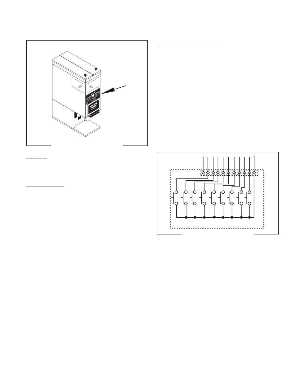
Membrane Switches (Models FPG-2 & G9-2 DBC)
Location:
The membrane switch is located on the front of the
hopper housing.
Test Procedures:
NOTE: Before continuing, check that the ribbon cable
is properly connected to the control board and not a
pin off in either direction.
1. Disconnect the dispenser from the power source.
2. Remove the rear panel and disconnect ribbon
cable.
3. Check for continuity of the switches using pin #1as
common.
FIG 58 MEMBRANE SWITCH
FIG 59 MEMBRANE SWITCH
Removal and Replacement
1. Disconnect the grinder from the power supply.
2. Remove the rear access panel.
3. Disconnect the membrane switch harness from the
control board.
4. Carefully peel the membrane switch from the front
of the switch bezel.
5. Remove any excess adhesive from the bezel sur-
face.
6. Remove the backing from the new membrane
switch.
7. Feed the membrane switch harness through the
openning and apply the new membrane switch to
the switch bezel.
8. Connect the switch harness to the control board.
1
11
SHIELD
SWITCH UNIT ASSY
B2
C4
C5
C6
A2
A1
C3
C2
C1
A1 - #5 Grind
A2 - #6 Stop
B2 - #10 Hidden Button "Right"
C1 - #2 Large Batch Size "Left"
C2 - #3 Medium Batch Size "Left"
C3 - #4 Small Batch Size "Left"
C4 - #9 Large Batch Size "Left"
C5 - #8 Medium Batch Size "Left"
C6 - #7 Small Batch Size "Left"
- #1 Nuetral
If continuity is not present when the appropriate switch
is pressed, the Membrane Switch must be replaced.
If continuity is present, chech the short harness going
to J6 on the Control Board.
To Control Board J6
41545 122209