Service (cont.) – Bunn G9-2T DBC User Manual
Page 51
51
SERVICE (Cont.)
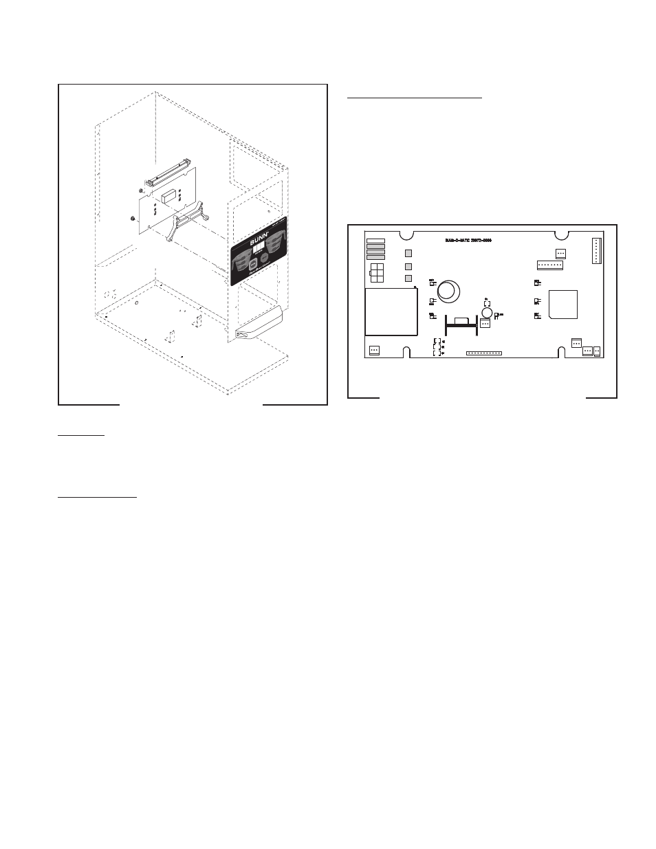
Control Board (Models FPG-2 & G9-2 DBC)
Location:
The control board is located inside the hopper
housing behind the membrane switch.
Test Procedure:
1. Check the continuity of the wiring between the
component and the control board.
2. Test the individual components before replacing
the control board.
FIG 55 CONTROL BOARD
FIG 56 CONTROL BOARD TERMINALS
Removal and Replacement
1. Disconnect the grinder from the power supply.
2. Remove the rear access panel.
3. Disconnect all harness plugs from the control
board.
4. Remove the two knurled nuts from the bottom of
the control board and remove the control board.
5. Refer to Fig 56 when connecting wires.
MOV4
MOV3
MOV2
MOV1
TH1
J1
J8
J5
J6
J3
J2
J4
J9
J10 J7
TH2
TH3
41545 122209