Service (cont.) – Bunn G9-2T DBC User Manual
Page 49
49
SERVICE (Cont.)
DIS
PEN
SE
TIM
E (S
eco
nds
)
DIS
PLA
Y
Incr
eas
e
Dec
reas
e
Rea
dou
t wi
ll be
dis
play
ed f
or 5 m
inut
es.
Tim
er c
an o
nly b
e ad
just
ed
whi
le re
ado
ut is
disp
laye
d.
+
WA
RN
ING
HAZ
ARD
OUS
VO
LTA
GE
UNP
LUG
GR
IND
ER
BEF
OR
E R
EM
OVI
NG
RIG
HT
DIS
PEN
SE
TIME
(SE
CO
NDS
)
3.2
6
10
15
20
25
30
32
3.2
.4
.4
1
1
2
2
3
3
4
6
10
15
20
25
30
32
4
LEF
T
HIG
H
UN
PLU
G G
RIN
DER
BEF
OR
E R
EM
OV
ING
WA
RN
ING
HAZ
ARD
OUS
VO
LTA
GE
HIGH
LOW
HIG
H
HIGH
LOW
LOW
LOW
O N
OFF
O N
OFF
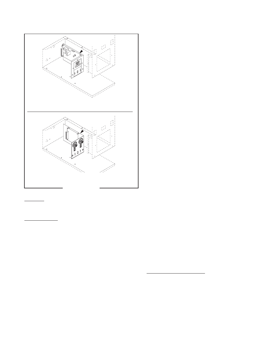
Location:
The timer is located in the grinder base.
Test Procedure:
1. Unplug the grinder.
2. Connect a voltmeter across contacts 1 & 2 of the
larger connector (P4) on the timer board. Plug-in
the grinder. The indication must be 120 volts ac for
120V models and 230 volts ac for 230V models.
3. Unplug the grinder.
4. Connect a voltmeter across contacts 2 & 6 of the
larger connector (P4) on the timer board. Plug-in
the grinder. When the control switch is in any posi-
tion except “OFF” (center), the indication must be
120 volts ac for 120V models and 230 volts ac for
230V models.
5. Unplug the grinder.
If voltage is present as described, proceed to #6.
If voltage is not present as described, refer to the Wiring
Diagram and check the grinder wiring harness.
P613
Digital Timer
Analog Timer
6. Connect a voltmeter across contacts 3 & 7 of the
larger connector (P4) on the timer board. Plug-in
the grinder. Momentarily press the Off/On/Start
switch to “START” (lower) position and release. The
indication must be 120 volts ac for 120V models
and 230 volts ac for 230V models.
7. Unplug the grinder.
If voltage is present as described, proceed to #8.
If voltage is not present as described, replace the
timer.
8. Connect a voltmeter across contacts 4 & 7 of the
larger connector (P4) on the timer board. Plug-in
the grinder. Place the hopper selector switch to
the left position. Momentarily press the Off/On/
Start switch to the “START” (lower) position and
release. The indication must be 120 volts ac for
120V models and 230 volts ac for 230V models and
should remain for the approximate timer setting.
9. Unplug the grinder.
If voltage is present as described, proceed to #10.
If voltage is not present as described, replace the
timer.
10. Connect a voltmeter across contacts 5 & 7 of the
larger connector (P4) on the timer board. Plug-in
the grinder. Place the hopper selector switch to
the right position. Momentarily press the Off/On/
Start switch to the “START” (lower) position and
release. The indication must be 120 volts ac for
120V models and 230 volts ac for 230V models and
should remain for the approximate timer setting.
11. Unplug the grinder.
If voltage is present as described, the timer is operat-
ing properly.
If voltage is not present as described, replace the
timer.
Removal and Replacement:
1. Separate the grinder wiring harness connectors
from the timer circuit board.
2. Remove the relay from the timer bracket.
3. Attach the relay to the new timer bracket.
4. Refer to the following illustration when reattaching
the connectors.
5. Refer to the Adjustments section to reset the vol-
ume dispensed.
Timer (Model G9-2)
FIG 52 TIMER
41545 122209