Bryant Induced-Combustion 4-Way Multipoise 310AAV User Manual
Page 41
11. If a greasy residue is present on blower wheel, remove wheel
from the blower housing and wash it with an appropriate
degreaser. To remove wheel:
NOTE:
Before disassembly, mark blower motor, and blower
housing so motor and each arm is positioned at the same location
during reassembly.
a. Disconnect capacitor wires and ground wire attached to
blower housing.
b. Remove screws securing cutoff plate and remove cutoff
plate from housing.
c. Loosen set screw holding blower wheel on motor shaft
(160+/-20 in-lb when reassembling).
d. Remove bolts holding motor to blower housing and slide
motor out of wheel (40+/-20 in-lb when reassembling).
e. Remove blower wheel from housing.
f. Clean wheel and housing.
12. Reassemble motor and blower by reversing steps 11f through
11a, finishing with 11a. Be sure to reattach ground wire to the
blower housing.
13. Verify that blower wheel is centered in blower housing and set
screw contacts the flat portion of the motor shaft. Loosen set
screw on blower wheel and reposition if necessary.
14. Spin the blower wheel by hand to verify that the wheel does
not rub on the housing.
15. Reinstall blower assembly in furnace.
16. Reinstall control box assembly in furnace.
UNIT DAMAGE HAZARD
Failure to follow this caution may shorten heat exchanger life.
Heating fan speed(s) MUST be adjusted to provide proper air
temperature rise as specified on the rating plate. Recom-
mended operation is at the midpoint of the rise range or
slightly above. Refer to
″SET TEMPERATURE RISE″ under
START-UP, ADJUSTMENT, and SAFETY CHECK.
NOTE:
Refer to Table 9 for motor speed lead relocation if leads
were not identified before disconnection.
17. Reconnect blower leads to furnace control. Refer to furnace
wiring diagram, and connect thermostat leads if previously
disconnected.
18. To check blower for proper rotation:
a. Turn on electrical supply.
ELECTRICAL SHOCK HAZARD
Failure to follow this warning could result in electrical shock,
personal injury, or death.
Blower access door switch opens 115-v power to furnace
control. No component operation can occur unless switch is
closed. Exercise caution to avoid electrical shock from
exposed electrical components when manually closing this
switch for service purposes.
b. Manually close blower access door switch.
NOTE:
If thermostat terminals are jumpered at the time blower
access door switch is closed, blower will run for 90 sec before
beginning a heating or cooling cycle.
c. Perform component self-test as shown at the bottom of the
SERVICE label, located on the front of blower access door.
d. Verify blower is rotating in the correct direction.
19. If furnace is operating properly, RELEASE BLOWER AC-
CESS DOOR SWITCH. Remove any jumpers or reconnect
any disconnected thermostat leads. Replace blower access
door.
20. Downflow or horizontal furnaces with vent pipe through
furnace only:
a. Install and connect short piece of vent pipe inside furnace
to existing vent.
b. Connect vent connector to vent elbow.
21. Reinstall casing door.
22. Turn on gas supply and cycle furnace through one complete
heating and cooling cycle. Verify the furnace temperature rise
as shown in
″Adjustments″ Section. Adjust temperature rise as
shown in
″Adjustments″ Section. If outdoor temperature is
below 70°F, turn off circuit breaker to outdoor unit before
running furnace in the cooling cycle. Turn outdoor circuit
breaker on after completing cooling cycle.
CLEANING HEAT EXCHANGER
The following steps should be performed by a qualified service
agency:
NOTE:
If the heat exchangers get a heavy accumulation of soot
and carbon, they should be replaced rather than trying to clean
them thoroughly. A build-up of soot and carbon indicates that a
problem exists which needs to be corrected, such as improper
adjustment of manifold pressure, insufficient or poor quality
combustion air, incorrect size or damaged manifold orifice(s),
improper gas, or a restricted heat exchanger. Action must be taken
to correct the problem.
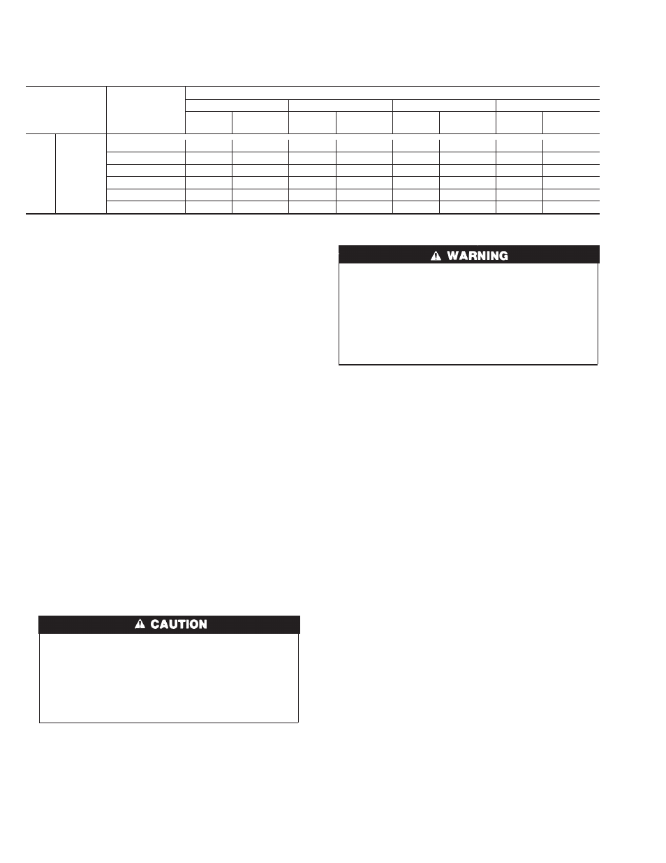
Table 12—Orifice Size* And Manifold Pressure For Gas Input Rate (Continued)
(Tabulated Data Based On 22,000 Btuh Per Burner, Derated 4 Percent For Each 1000 Ft Above Sea Level)
ALTITUDE
RANGE
(FT)
AVG GAS
HEAT VALUE
AT ALTITUDE
(BTU/CU FT)
SPECIFIC GRAVITY OF NATURAL GAS
0.58
0.60
0.62
0.64
Orifice
No.
Manifold
Pressure
Orifice
No.
Manifold
Pressure
Orifice
No.
Manifold
Pressure
Orifice
No.
Manifold
Pressure
U.S.A.
Only
9001
to
10,000
600
43
2.7
43
2.8
43
2.9
43
3.0
625
43
2.5
43
2.6
43
2.6
43
2.7
650
43
2.3
43
2.4
43
2.4
43
2.5
675
43
2.1
43
2.2
43
2.3
43
2.3
700
48
3.7
43
2.0
43
2.1
43
2.2
725
48
3.5
48
3.6
48
3.7
43
2.0
* Orifice numbers 43 are factory installed
40
→
→
→