Bryant Induced-Combustion 4-Way Multipoise 310AAV User Manual
Page 34
f. Set thermostat to call for heat.
g. Jumper R and W thermostat connections on furnace control
board to start furnace.
h. Remove regulator seal cap and turn regulator adjusting
screw counterclockwise (out) to decrease input rate of
clockwise (in) to increase input rate.
i. Install regulator seal cap.
j. Leave manometer or similar device connected and proceed
to Step 4.
NOTE:
DO NOT set manifold pressure less than 3.2-in wc or
more than 3.8-in. wc for natural gas at sea level. If manifold
pressure is outside this range, change main burner orifices or refer
to Table 12 or 13.
NOTE:
If orifice hole appears damaged or it is suspected to have
been redrilled, check orifice hole with a numbered drill bit of
correct size. Never redrill an orifice. A burr-free and squarely
aligned orifice hole is essential for proper flame characteristics.
4. Verify natural gas input rate by clocking meter.
NOTE:
Gas valve regulator adjustment cap must be in place for
proper input to be clocked.
a. Turn off all other gas appliances and pilots served by the
meter.
b. Run furnace for 3 minutes in heating operation.
c. Measure time (in sec) for gas meter to complete 1 revolu-
tion and note reading. The 2 or 5 cubic feet dial provides a
more accurate measurement of gas flow.
d. Refer to Table 10 for cubic ft of gas per hr.
e. Multiply gas rate (cu ft/hr) by heating value (Btu/cu ft) to
obtain input.
If clocked rate does not match required input from Step 1, increase
manifold pressure to increase input or decrease manifold pressure
to decrease input. Repeat steps b through e until correct input is
achieved. Reinstall regulator seal cap on gas valve.
5. Set temperature rise.
The furnace must operate within the temperature rise ranges
specified on the furnace rating plate. Do not exceed tempera-
ture rise range specified on unit rating plate. Determine the
temperature rise as follows:
NOTE:
Blower access door must be installed when taking tem-
perature rise reading. Leaving blower access door off will result in
incorrect temperature measurements.
a. Place thermometers in return and supply ducts as close to
furnace as possible. Be sure thermometers do not see
radiant heat from heat exchangers. Radiant heat affects
temperature rise readings. This practice is particularly
important with straight-run ducts.
b. When thermometer readings stabilize, subtract return-air
temperature from supply-air temperature to determine air
temperature rise.
NOTE:
Blower access door must be installed for proper tempera-
ture rise measurement.
NOTE:
If the temperature rise is outside this range, first check:
1.) Gas input for heating operation.
2.) Derate for altitude if applicable.
3.) Return and supply ducts for excessive restrictions causing static
pressures greater than 0.50-in. wc.
4.) Dirty filter.
ELECTRICAL SHOCK HAZARD
Failure to follow this warning could result in personal injury
or death.
Disconnect 115-v electrical power before changing speed tap.
c. Adjust air temperature rise by adjusting blower speed.
Increase blower speed to reduce temperature rise. Decrease
blower speed to increase temperature rise.
Table 8–Altitude Derate Multipler for U.S.A.
ALTITUDE
(FT)
PERCENT
OF DERATE
DERATE MULTIPLIER
FACTOR*
0–2000
0
1.00
2001–3000
8–12
0.90
3001–4000
12–16
0.86
4001–5000
16–20
0.82
5001–6000
20–24
0.78
6001–7000
24–28
0.74
7001–8000
28–32
0.70
8001–9000
32–36
0.66
9001–10,000
36–40
0.62
* Derate multiplier factors are based on midpoint altitude for altitude range.
→
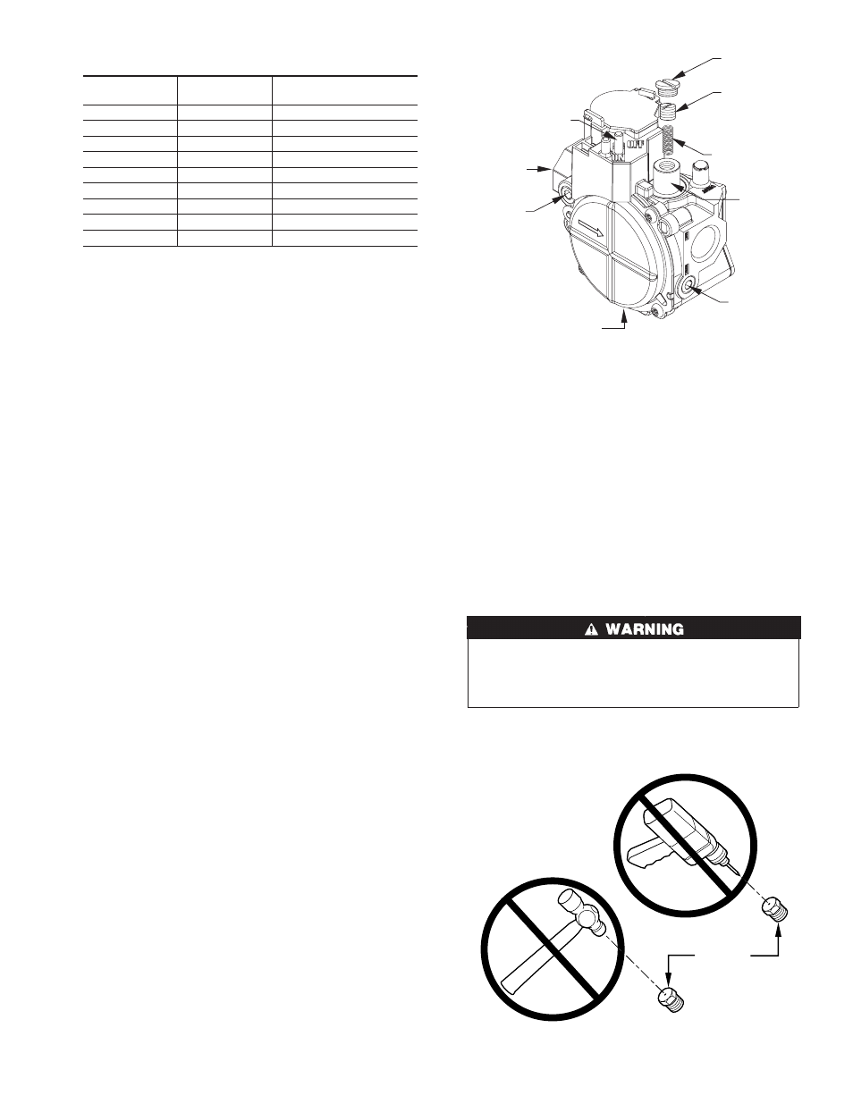
Fig. 46—Gas Control Valve
A04166
REGULATOR
SEAL CAP
REGULATOR
ADJUSTMENT
SCREW
REGULATOR SPRING
GAS PRESSURE
REGULATOR
ADJUSTMENT
MANIFOLD
PRESSURE TAP
INLET
PRESSURE TAP
ON/OFF SWITCH
1/2˝ NPT INLET
1/2˝ NPT OUTLET
Fig. 47—Orifice Hole
A93059
BURNER
ORIFICE
33
→