Fig. 49—service label – Bryant Induced-Combustion 4-Way Multipoise 310AAV User Manual
Page 37
ELECTRICAL CONTROLS AND WIRING
ELECTRICAL SHOCK HAZARD
Failure to follow this warning could result in personal injury
or death.
There may be more than one electrical supply to the furnace.
Check accessories and cooling unit for additional electrical
supplies that must be shut off during furnace servicing.
The electrical ground and polarity for 115-v wiring must be
properly maintained. Refer to Fig. 25 for field wiring information
and to Fig. 45 for furnace wiring information.
NOTE:
If the polarity is not correct, the STATUS LED on the
control will flash rapidly and prevent the furnace from heating.
The control system also requires an earth ground for proper
operation of the control and flame-sensing electrode.
The 24-v circuit contains an automotive-type, 3-amp fuse located
on the control. (See Fig. 24.) Any shorts of the 24-v wiring during
installation, service, or maintenance will cause this fuse to blow. If
fuse replacement is required, use ONLY a 3-amp fuse. The control
LED will display status code 24 when fuse needs to be replaced.
Proper instrumentation is required to service electrical controls.
The control in this furnace is equipped with a Status Code LED
(Light-Emitting Diode) to aid in installation, servicing, and
troubleshooting. It can be viewed through the sight glass in blower
access door. The furnace control LED is either ON continuously,
rapid flashing, or a code composed of 2 digits. The first digit is the
number of short flashes, the second digit is the number of long
flashes.
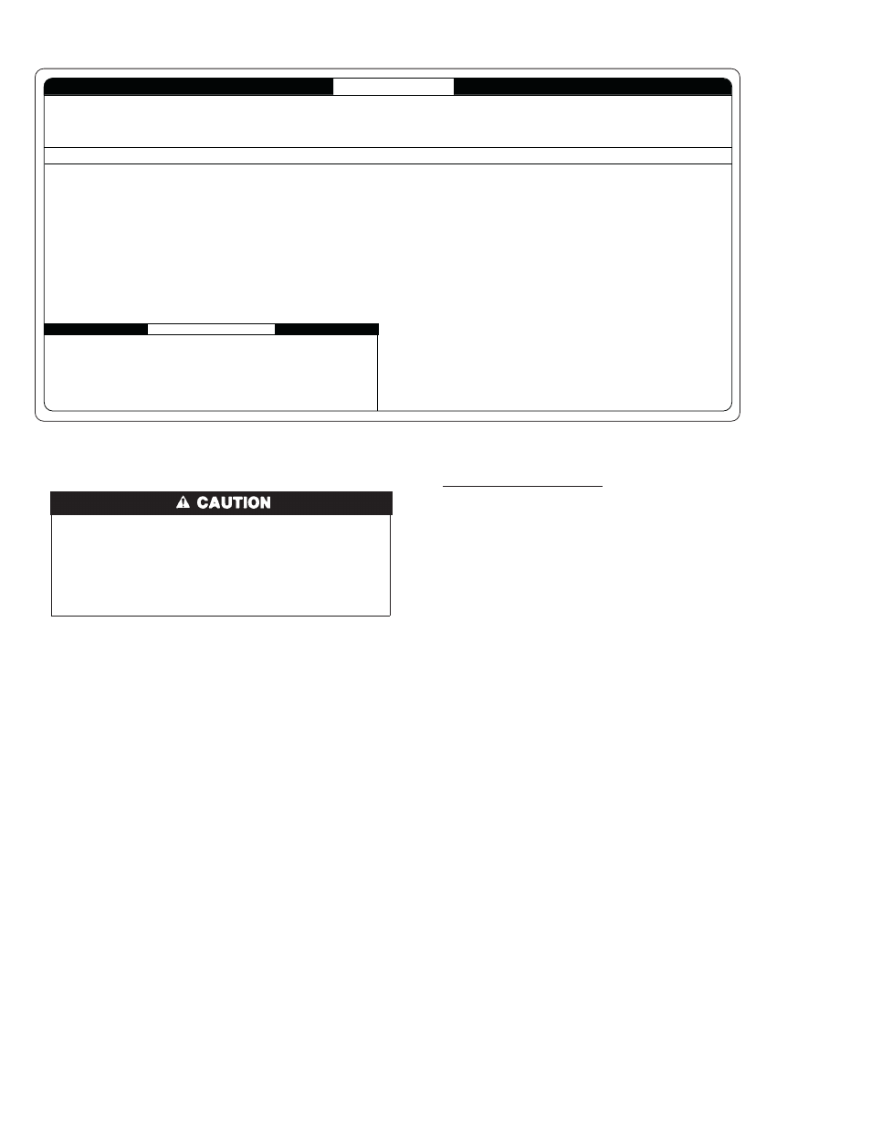
For an explanation of status codes, refer to service label located on
blower access door or Fig. 49, and the troubleshooting guide which
can be obtained from your distributor. The furnace control will
store 1 status code for 72 hours.
See Fig. 53, a brief Troubleshooting Guide.
For Controls With a Red LED
The stored status codes WILL be erased from the control memory,
if 115- or 24-v power is interrupted.
1. To retrieve the status code, proceed with the following:
NOTE:
NO thermostat signal may be present at control, and all
blower-OFF delays must be completed.
a. Leave 115-v power to furnace turned on.
b. Remove outer access door.
c. Look into blower access door sight glass for current LED
status. DO NOT remove blower access door or terminate
115-v power to control or status code will be lost.
d. BRIEFLY remove insulated terminal wire from the draft
safeguard switch (DSS) until LED goes out (1 to 2 sec),
then reconnect it.
2. When above items have been completed, the LED flashes
status code 4 times. Record this status code for further
troubleshooting.
3. Component self-test will begin. Refer to COMPONENT
TEST section for complete test sequence.
4. Check LED status.
5. Refer to the SERVICE label on the front of the blower access
door for more information.
6. Check LED status. If no previous fault is in history, control
will flash status code 11.
7. If
LED
status
indicates
proper
operation,
RELEASE
BLOWER ACCESS DOOR SWITCH, reattach wire to
″R″
terminal on furnace control board, replace blower access door,
and replace burner access door.
→
Fig. 49—Service Label
A04223
To initiate the component test sequence, shut OFF the room thermostat or disconnect the "R"
thermostat lead. Briefly short the TEST/TWIN terminal to the "Com 24V" terminal. Status LED
will flash code and then turn ON the inducer motor. The inducer motor will run for the entire
component test. The hot surface ignitor, blower motor fan speed (on AMBER LED boards
only) blower motor-heat speed, and blower motor-cool speed will be turned ON for 10-15
seconds each. Gas Valve and Humidifier will not be turned on.
CONTINUOUS OFF - Check for 115VAC at L1 and L2, and 24VAC at SEC-1 and SEC-2.
CONTINUOUS ON - Control has 24VAC power.
RAPID FLASHING - Line voltage (115VAC) polarity reversed. If twinned, refer to twinning kit instructions.
LED CODE
STATUS
11 NO PREVIOUS CODE - Stored status code is erased automatically after 72 hours. On
RED LED boards stored status codes can also be erased when power
(115 VAC or 24 VAC) to control is interrupted.
12 BLOWER ON AFTER POWER UP (115 VAC or 24 VAC) -Blower runs for 90 seconds,
if unit is powered up during a call for heat (R-W closed) or R-W opens during blower
on-delay.
13 LIMIT CIRCUIT LOCKOUT - Lockout occurs if the limit, draft safeguard, flame rollout, or
blocked vent switch (if used) is open longer than 3 minutes.
- Control will auto reset after three hours. - Refer to #33.
14 IGNITION LOCKOUT - Control will auto-reset after three hours. Refer to #34.
21 GAS HEATING LOCKOUT - Control will NOT auto reset.
Check for: - Mis-wired gas valve
-Defective control (valve relay)
22 ABNORMAL FLAME-PROVING SIGNAL - Flame is proved while gas valve is de-
energized. Inducer will run until fault is cleared. Check for: - Leaky gas valve
- Stuck-open gas valve
23 PRESSURE SWITCH DID NOT OPEN Check for:
- Obstructed pressure tubing. - Pressure switch stuck closed.
24 SECONDARY VOLTAGE FUSE IS OPEN Check for:
- Short circuit in secondary voltage (24VAC) wiring.
If status code recall is needed, briefly remove then reconnect one main limit wire to display stored status code. On RED LED boards do not remove power or blower door before initiating status code recall. After
status code recall is completed component test will occur.
327596-101 REV. B
31
PRESSURE SWITCH DID NOT CLOSE OR REOPENED - If open longer than five minutes,
inducer shuts off for 15 minutes before retry. Check for: - Excessive wind
- Proper vent sizing - Defective inducer motor
- Low inducer voltage (115VAC) - Defective pressure switch
- Inadequate combustion air supply - Disconnected or obstructed pressure tubing
- Low inlet gas pressure (if LGPS used) - Restricted vent
If it opens during blower on-delay period, blower will come on for the selected blower
off-delay.
33 LIMIT CIRCUIT FAULT - Indicates a limit, draft safeguard, flame rollout, or blocked vent
switch (if used) is open. Blower will run for 4 minutes or until open switch remakes
whichever is longer. If open longer than 3 minutes, code changes to lockout #13.
If open less than 3 minutes status code #33 continues to flash until blower shuts off.
Flame rollout switch and BVSS require manual reset. Check for: - Restricted vent
- Proper vent sizing - Loose blower wheel. - Excessive wind
- Dirty filter or restricted duct system.
- Defective blower motor or capacitor. - Defective switch or connections.
- Inadequate combustion air supply (Flame Roll-out Switch open).
34 IGNITION PROVING FAILURE - Control will try three more times before lockout #14
occurs. If flame signal lost during blower on-delay period, blower will come on for the
selected blower off-delay. Check for: - Flame sensor must not be grounded
- Oxide buildup on flame sensor (clean with fine steel wool).
- Proper flame sense microamps (.5 microamps D.C. min., 4.0 - 6.0 nominal).
- Gas valve defective or gas valve turned off - Manual valve shut-off
- Defective Hot Surface Ignitor - Control ground continuity
- Low inlet gas pressure - Inadequate flame carryover or rough ignition
- Green/Yellow wire MUST be connected to furnace sheet metal
45 CONTROL CIRCUITRY LOCKOUT Auto-reset after one hour lockout due to;
- Gas valve relay stuck open - Flame sense circuit failure - Software check error
Reset power to clear lockout. Replace control if status code repeats.
SERVICE
COMPONENT TEST
EACH OF THE FOLLOWING STATUS CODES IS A TWO DIGIT NUMBER WITH THE FIRST DIGIT DETERMINED BY THE NUMBER OF SHORT FLASHES AND THE SECOND DIGIT BY THE NUMBER OF LONG FLASHES.
36
→
→