Fig. 24—furnace control – Bryant Induced-Combustion 4-Way Multipoise 310AAV User Manual
Page 22
Electrical Box on Furnace Casing Side
See Fig. 23.
FIRE OR ELECTRICAL SHOCK HAZARD
Failure to follow this warning could result in personal injury,
death, or property damage.
If field-supplied manual disconnect switch is to be mounted
on furnace casing side, select a location where a drill or
fastener cannot damage electrical or gas components.
1. Select and remove a hole knockout in the casing where the
electrical box is to be installed.
NOTE:
Check that duct on side of furnace will not interfere with
installed electrical box.
2. Remove the desired electrical box hole knockout and position
the hole in the electrical box over the hole in the furnace
casing.
3. Fasten the electrical box to casing by driving two field-
supplied screws from inside electrical box into casing steel.
4. Remove and save two screws holding J-Box. (See Fig. 22.)
5. Pull furnace power wires out of 1/2-inch diameter hole in
J-Box. Do not loosen wires from strain-relief wire-tie on
outside of J-Box.
6. Route furnace power wires through holes in casing and
electrical box and into electrical box.
7. Pull field power wires into electrical box.
8. Remove cover from furnace J-Box.
9. Route field ground wire through holes in electrical box and
casing, and into furnace J-Box.
10. Reattach furnace J-Box to furnace casing with screws re-
moved in Step 4.
11. Secure field ground wire to J-Box green ground screw.
12. Complete electrical box wiring and installation. Connect line
voltage leads as shown in Fig. 25. Use best practices (NEC in
U.S. and CSA C22.1 in Canada) for wire bushings, strain
relief, etc.
13. Reinstall cover to J-Box. Do not pinch wires between cover
and bracket.
POWER CORD INSTALLATION IN FURNACE J-BOX
NOTE:
Power cords must be able to handle the electrical require-
ments listed in Table 5. Refer to power cord manufacturer’s
listings.
1. Remove cover from J-Box.
2. Route listed power cord through 7/8-inch diameter hole in
J-Box.
3. Secure power cord to J-Box bracket with a strain relief
bushing or a connector approved for the type of cord used.
4. Secure field ground wire to green ground screw on J-Box
bracket.
5. Connect line voltage leads as shown in Fig. 25.
6. Reinstall cover to J-Box. Do not pinch wires between cover
and bracket.
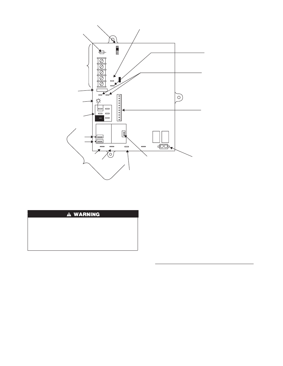
Fig. 24—Furnace Control
A02100
BL
W
NUETRAL
ST
A
TUS CODE LED
SEC-2 SEC-1
EAC-2 L2
FUSE 3-AMP
0.5 AMP@24VAC
HUM
TEST/TWIN
G Com
W
Y R
24V
120 180
90 150
BLOWER OFF-DELAY
PL
T 1
COOL HEA
T
SPARE-1 SPARE-2
EAC-1
1-AMP@
115VAC
PR-1
L1
PL2 1
24-V THERMOSTAT
TERMINALS
3-AMP FUSE
LED OPERATION &
DIAGNOSTIC LIGHT
115-VAC(L2)NEUTRAL
CONNECTIONS
COOL
HEAT
SPARE-1
SPARE-2
BLOWER SPEED
SELECTION TERMINALS
EAC-1 TERMINAL
(115-VAC 1.0 AMP MAX.)
115 VAC (L1) LINE
VOLTAGE CONNECTION
PL2-HOT SURFACE
IGNITER & INDUCER
MOTOR CONNECTOR
PL1-LOW VOLTAGE MAIN
HARNESS CONNECTOR
TRANSFORMER 24-VAC
CONNECTIONS
HUMIDIFIER TERMINAL
(24-VAC 0.5 AMP MAX.)
TWINNING AND/OR
COMPONENT TEST
TERMINAL
BLOWER OFF-DELAY
J2
J2 JUMPER
PL
T
21
→
→
→