Din front/rear-mount 24, Din front-mount 24, Installation – Pioneer AVIC-X3-II User Manual
Page 24: Din front/rear-mount, Din front-mount
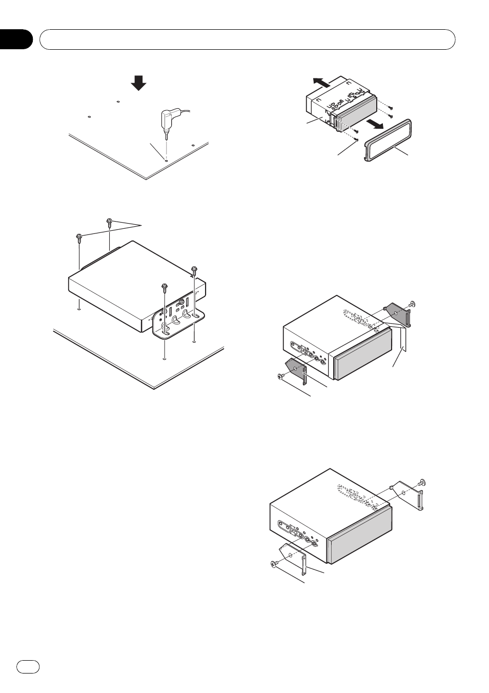
Drill holes of
between 4 mm and
4.5 mm in diameter.
3
Secure it firmly using the self-tapping
screws.
Self-tapping screw
(6 mm 16 mm)
DIN Front/Rear-mount
The display unit can be properly installed
either from
“Front” (conventional DIN Front-
mount) or
“Rear” (DIN Rearmount installation,
using threaded screw holes at the sides of unit
chassis). For details, refer to the following illu-
strated installation methods.
Before installing the unit
% Remove the frame and the holder.
Extend top and bottom of the frame outwards
to remove the frame. And then loosen the
screws (2 mm × 3 mm) to remove the holder.
! When reattaching the frame, push the
frame onto the unit until it clicks after reat-
taching the holder.
Frame
Screw
(2 mm 3 mm)
Holder
DIN Front-mount
Installation with the rubber bush
1
Decide the position of the side brack-
ets.
# When installing in a shallow space, change
the position of side brackets (small). In this case,
stick conceal tape on parts that protrude from the
dashboard. (The frame is not used.)
Side bracket (small)
Conceal tape
Screw for fixing the side bracket (5 mm 6 mm)
# If you prefer an off-set installation in which the
front panel is pushed further back, when there is
a space available at the back of the unit, use the
side brackets (large).
Side bracket (large)
Screw for fixing the side bracket (5 mm 6 mm)
Installation
Engb
24
Section
04