2 set commands, Ata6264 [preliminary – Atmel ATA6264 User Manual
Page 70
70
4929B–AUTO–01/07
ATA6264 [Preliminary]
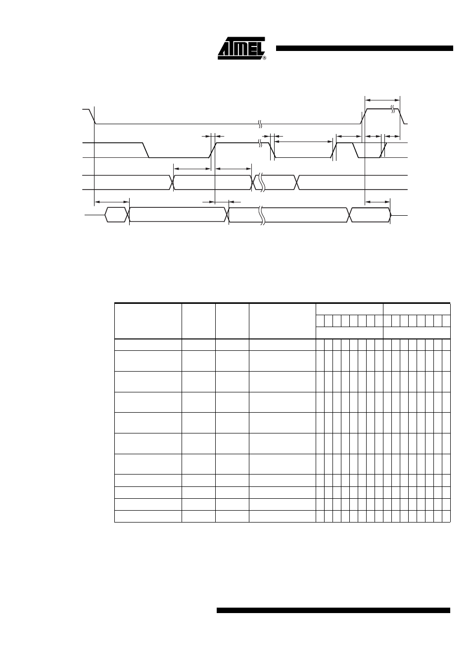
Figure 22-1. Timing Serial Interface
22.2
Set Commands
After a reset due to the watchdog or undervoltage, all internal control registers and decoded sig-
nals are set to their default values.
Serial interface commands other than those listed in
tion of measurements via AMUX, cause pin UZP to be switched to tristate, and IASG sources to
be deactivated. The status of the latches does not change.
7. (< 400 ns)
5. (> 20 ns)
6. (> 20 ns)
4. (< 20 ns)
not
defined
not
defined
not defined
LSB
MSB
#16
#1
LSB
MSB
SSQ
SCLK
3. (< 20 ns)
14. (> 40 ns)
8. (< 40 ns)
9. (< 40 ns)
1. (> 100 ns)
2. (> 100 ns)
10. (> 1.5 µs)
MISO
MOSI
Table 22-2.
Set of Serial Interface Commands
Command
Latch
Hex
Description
MSByte
LSByte
7 6 5 4 3 2 1 0 7 6 5 4 3 2 1 0
Command
Option and Data
NOP
No
0000
0 0 0 0 0 0 0 0 0 0 0 0 0 0 0 0
Key latch
Yes
3xxx
0 0 1 1 x x x x x x x x x x x x
Watchdog No
6xxx
0 1 1 0 x x x x x x x x x x x x
Switch commands
Yes
9xxx
1 0 0 1 x x x x x x x x x x x x
Initial programming
N/A
Axxx
1 0 1 0 x x x x x x x x x x x x
Diagnosis
No
Cxxx
1 1 0 0 x x x x x x x x x x x x
IASG
No
Fxxx
1 1 1 1 x x x x x x x x x x x x
Test mode 1
No
55AA
0 1 0 1 0 1 0 1 1 0 1 0 1 0 1 0
Test mode 2
No
AA55
1 0 1 0 1 0 1 0 0 1 0 1 0 1 0 1
Test mode 3
No
5500
0 1 0 1 0 1 0 1 0 0 0 0 0 0 0 0
Test-mode enable
No
5A5A
0 1 0 1 1 0 1 0 0 1 0 1 1 0 1 0