Ata6264 [preliminary – Atmel ATA6264 User Manual
Page 44
44
4929B–AUTO–01/07
ATA6264 [Preliminary]
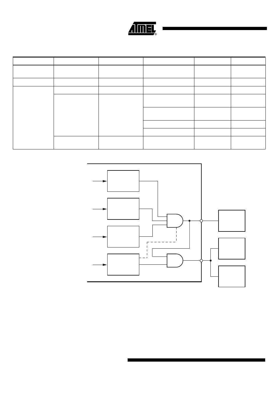
Figure 15-4. Application Example
Necessary for operation:
V
EVZ
= 5.5V to 40V, V
PERI
= 1V to 5.5V, V
INT
= 3.7V to 5.47V
Operating conditions of all other supply pins:
V
K30
, V
SAT
, and V
CORE
are within functional range limits, T
j
= –40°C to 150°C
Other pins:
As defined in
Section 4. ”Functional Range” on page 8
Table 15-1.
Reset Truth Table
VPERI
VCORE
VEVZ
WATCHDOG
RESQ
RESQ2
< 1V
X
X
X
Undefined (low
via resistor)
Undefined (low
via resistor)
1V to V
VPERI
= OK
X
X
X
Low
Low
> V
VPERI
= OK
V
VCORE
= Not OK
X
X
Low
Low
V
VCORE
= OK
EVZGOOD = high
(V
EVZ
= OK)
After startup
(no trigger has occurred)
High
Low
Correctly triggered
(trigger occurred 1
st
time)
High
Low -> high
Correctly triggered
High
High
Incorrectly triggered
High -> low
High -> low
X
EVZGOOD = low
(V
EVZ
= Not OK)
X
Low
Low
V
EVZ
V
CORE
V
PERI
WD-logic
Watchdog is
triggered
Other
peri
(3.3V)
Safety system
monitoring
microcontroller
(3.3V)
Microcontroller
dual voltage
supply
(1.88V, 3.3V)
V
CORE
is above
reset
"threshold" and
below overvoltage
V
PERI
is above
reset
"threshold" and
below overvoltage
V
EVZ
is above
reset
"threshold"
RESQ2
RESQ