3 start-up and power-down procedure, Ata6264 [preliminary – Atmel ATA6264 User Manual
Page 14
14
4929B–AUTO–01/07
ATA6264 [Preliminary]
5.3
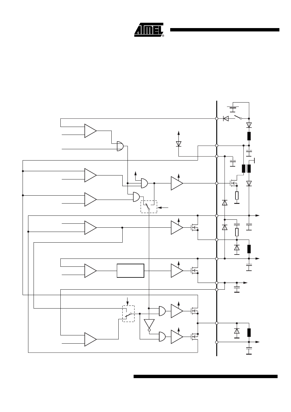
Start-up and Power-down Procedure
The ATA6264 is powered via the pin K30 (battery voltage) and via a diode or a resistor it is con-
nected to the ignition key line K15. In order to detect an interruption on one of these pins
correctly, resistors are implemented at these pins. Normally, the main supply pin of ATA6264 is
pin K30. In the case of a missing or a too-low voltage at pin K30, the whole IC is supplied from
the backup power supply capacitor hooked up to pin EVZ.
Figure 5-3.
Block Diagram Start-up and Power-down Procedure
VCP
VCP
K30
EVZ
VEVZ
V
VSAT
V
VPERI
Comp
VEVZ
K15GOOD
V
K15
= 3V to 4.15V
(40 mV to 175mV Hysteresis)
Serial interface
(KEY - LATCH)
VSAT
VCP
Comp
CORE_EN
V
PERI
= 1.25V to 1.7V
(50 mV to 150 mV Hysteresis)
Comp
VSATGOOD
V
SAT
= 6.77V to 7.2V
(200 mV to 500 mV Hysteresis)
Comp
V
EVZ
V
CP
K15
K30
CP
GEVZ
EVZEN
CORESWAP
5V
IREF lost
signal
V
K30
= 3.85V to 5V
(50 mV to 150 mV Hysteresis)
Power
sequencing
VSAT
driver
SVSAT
EVZ
V
VCORE
VCORE
SVCORE
VK30
IP
VEVZ
driver
Comp
K30GOOD
VCORE
driver
VCore
driver
VPERI
driver
VPERI
SVPER
IP
V
K30
= 6.1V to 8.1V (ON)
(0.5V to 1V Hysteresis)
Comp
EVZGOOD
V
EVZ
= 7.5V to 9V (ON)
V
EVZ
= 5.5V to 6.2V (OFF)