Lin/iso 9141 interfaces, Ata6264 [preliminary – Atmel ATA6264 User Manual
Page 54
54
4929B–AUTO–01/07
ATA6264 [Preliminary]
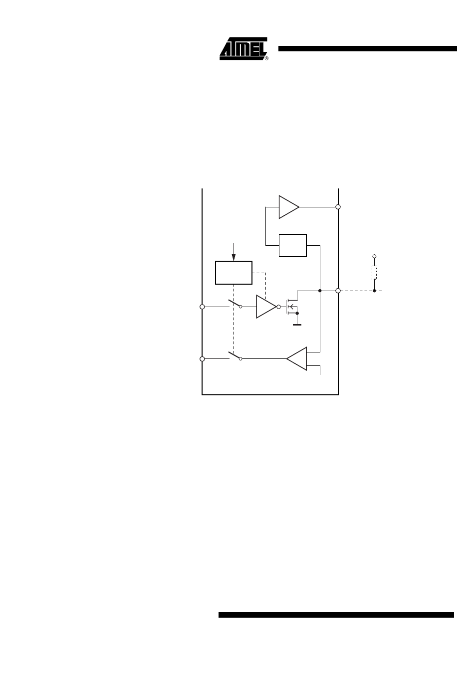
17. LIN/ISO 9141 Interfaces
The ATA6264 includes two complete ISO 9141 interfaces. Interface #1 is controlled via the pins
RxD1 and TxD1, interface #2 is controlled via the pins RxD2 and TxD2. In order to support both
ISO9141 and LIN bus requirements, interface #1 can be configured during initial programming.
In applications where one or both ISO9141 interfaces are not needed, the output transistors of
K1 and K2 may be used as simple low-side transistors, switched on or off by the serial interface.
In this mode, a diagnosis of the pins K1 and K2 via the analog multiplexer is possible. The K1
and K2 outputs include an internal current limitation and overtemperature protection circuit.
Figure 17-1. Functional Principle of the LIN/ISO 9141 Interfaces
Necessary for operation:
V
EVZ
= 9V to 40V, V
K30
= 5.5V to 40V, V
VPERI
> Reset threshold, V
VCORE
> Reset threshold,
V
VINT
= 3.7V to 5.47V
Operating conditions of all other supply pins:
V
VSAT
is within functional range limits, T
j
= –40°C to +150°C
Other pins:
As defined in
Section 4. ”Functional Range” on page 8
-
+
Analog
MUX
Mode
select
Serial
interface
K30
0.5
×
V
K30
GNDB
UZP
RXD
TXD
µC Analog input
K