Ata6264 [preliminary – Atmel ATA6264 User Manual
Page 16
16
4929B–AUTO–01/07
ATA6264 [Preliminary]
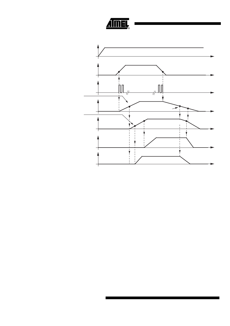
Figure 5-4.
Start-Up and Power-Down Procedure if V
VCORE
Programmed to Be 5V or 2.5V
5.3.3
Start-up Procedure if V
VCORE
Programmed to Be 1.88V
Phase1: After switching on the ignition key, the K15 voltage will appear at pin K15. If, in addi-
tion, the voltage at pin K30 is larger than 3.85V to 5V, the EVZ regulator will be enabled. The
signal K15GOOD can be replaced by the serial interface command KEYLATCH which can be
set by the serial interface.
Phase2: If VEVZ is larger than 7.5V to 9V, the VSAT regulator starts operating.
Phase3: After VVSAT has reached 6.77V to 7.2V, the VPERI regulator starts working.
Phase4: If VVPERI is higher than 1.25V to 1.7V, the VCORE regulator will be enabled.
t
V
K30
3V to 4.15V
3V to 4.15V
5.5V to 6.2V
too low EVZ voltage
VSAT goes into On Mode
charge pump deactivated
6.77V to 7.2V
7V to 6.27V
7.5V to 9V
V
GEVZ
V
EVZ
V
VSAT
V
K15
V
VCORE
V
VPERI
t
t
t
t
t
t
Threshold to enable
VCORE regulator
Threshold to start
VCORE regulator