Amux (analog multiplexer for voltage measurements), Ata6264 [preliminary – Atmel ATA6264 User Manual
Page 62
62
4929B–AUTO–01/07
ATA6264 [Preliminary]
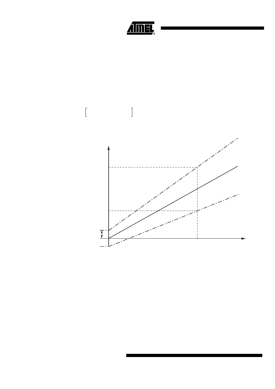
19. AMUX (Analog Multiplexer for Voltage Measurements)
Various voltages and the chip temperature inside of the ATA6264 can be measured at the ana-
log measurement output UZP. Different voltage dividers ensure that the values of the measured
voltages at UZP are in the range of 0V to V
PERI
. To select a specific measurement, a serial inter-
face command has to be sent to the ATA6264.
For the list of measurable voltages and temperatures, refer to
Section 22. ”Serial Interface Com-
. The overall accuracy of the measurement part inside the ATA6264 can be
calculated using the following formula:
Figure 19-1. AMUX Tolerances
In order to describe the behavior of the whole measurement properly, the tolerance of the volt-
age-divider ratio (ratio tolerance) and the offset tolerance of the UZP buffer (V
UZPoffset
) are
defined in separate points. The UZP buffer is defined in the following section.
Necessary for operation:
V
EVZ
= 8V to 40V or V
CP
= 10V to 50V, V
VINT
= 3.7V to 5.47V
Operating conditions of all other supply pins:
V
K30
, V
VSAT
, V
VPERI
and V
VCORE
are within functional range limits, T
j
= –40°C to +150°C
Other pins:
As defined in
Section 4. ”Functional Range” on page 8
V
UZP
V
meas
ratio
ratio
tolerance
±
--------------------------------------------------------
V
UZPoffset
±
=
V
UZP_max
V
in
V
UZP_offset
V
UZP_min
Vmeas
typ.
min.
max.
V
UZP