2 options, 4general information, 5id plate and technical data – Pfannenberg DTFI 9021 User Manual
Page 11: 6safety, 7function 7.1 principles of function, 2 condensate
085 408 065c
11
3
Scope of delivery and options
3.1
Scope of delivery
The Scope of delivery includes:
• cooling unit (with connection for door contact switch)
• Enclosed package (among other things sealing profile,
faste-ning material, electrical plug-type connectors)
• special accessories, if applicable.
3.2
Options
• Options on request or in accordance with the catalogue.
4
General Information
• Old devices can be properly disposed of by Pfannenberg.
They must be sent to one of our works shipment/postage paid.
• All cooling units produced by Pfannenberg are free from
–
siliconecompounds,
–
PCB,
–
PCT,
–
asbestos,
–
formaldehyde,
–
cadmium,
–
substances impairing wetting.
• Every cooling unit is checked to ensure that it is tight according
to the provisions of UVV-BGV D4 (German regulations covering
accident prevention).
• Prior to delivery the electrical safety of every cooling unit is
factory tested. This means that, in accordance with UVV-BGV
A2, §5 (4), the operating company is released from the obliga-
tion to arrange for a test of the electrical part of the cooling unit
before initial start of operation.
5
ID Plate and Technical Data
For installation and maintenance, note the data on the ID plate; it is
to be found on the back of the cooling unit casing
The technical details applicable to the cooling unit are in the
supplement.
6
Safety
Cooling units produced by Pfannenberg are designed for
dissipating heat from switch cabinets (IP 54). During each cooling
process condensate can be produced. The cooling unit is only
suitable for stationary operation.
The cooling unit may only be used under the ambient conditions
specified on the enclosed sheet.
The cooling unit is to a large measure maintenance-free (see Section
11).
Every other use is considered as non-authorized use making any
warranty null and void.
The electrical equipment must be regularly checked. Any faults
such as loose connections or scorched cables must be removed
immediately.
Work on the cooling system and on electrical components may only
be carried out by authorized specialist personnel.
Compliance with applicable safety and environmental regulations
is mandatory.
Hazard!
Isolate the cooling unit from the mains before carrying out
any cleaning or maintenance operations.
Only original spare parts may be used.
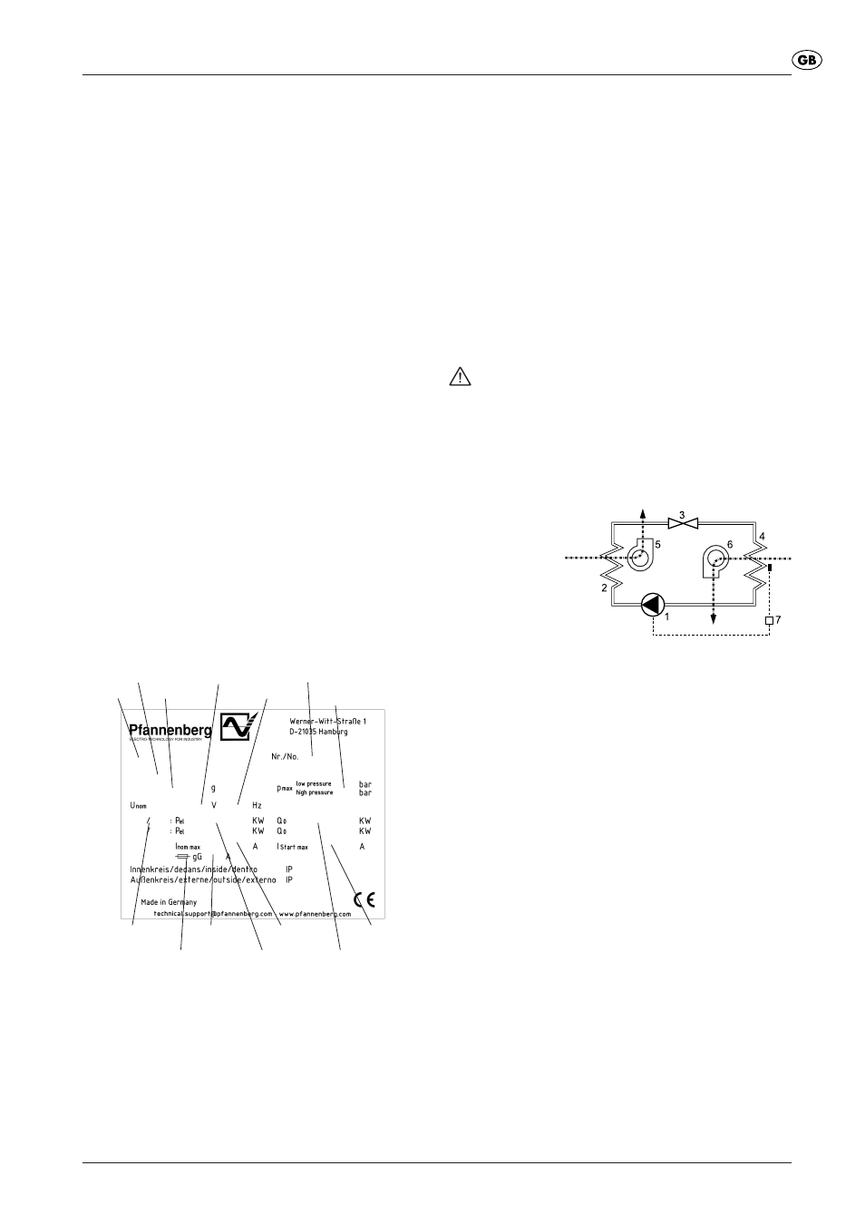
7
Function
7.1
Principles of function
1
Compressor
2
Heat exchanger
(condenser)
3
Expansion device
4
Heat exchanger
(evaporator)
5
fan, exterior circulation
6
fan, inner circulation
7
Electronic control system with temperature sensor
The compressor (1) compresses the refrigerant until high
pressure is achieved. During this process temperature increases.
In the condenser (2) heat is dissipated to ambient air, the coolant
becoming liquid. The condenser fan (5) of the condensator takes
ambient air in through the condenser, then it releases the air.
The pressure of the coolant drops as it passes through the
expansion device (3). In the evaporator (4) the coolant absorbs
heat from the air in the switch cabinet and evaporates. Thus, the
air in the switch cabinet cools down. At the same time the air
inside the switch cabinet is being dehumidified. The evaporator
fan (6) sucks the air out of the switch cabinet via the
evaporator, the cooled air flows back to the switch cabinet.
The cooling unit is electronically controlled. For that purpose a
temperature sensor records the temperature of the air inside the
switch cabinet (7).
The refrigerant is not detrimental to the ozonosphere; it is hardly
combustible.
7.2
Condensate
During cooling on the evaporator the moisture removed from the air
is collected as condensate. In order to avoid any damage to the
switch cabinet and the cooling unit, the condensate must be
discharged.
The condensate is discharged in the following way:
• In case of normal condensate drainage a reservoir collects the
condensate which is then drained by means of a hose.
Always ensure that the condensate is drained properly (safety-
drainage).
Excessive condensation can occur if, for example, the switch
cabinet is not sealed or if the internal temperature of the switch
cabinet is frequently below the dew point.
unit type
refrigerant
nominal voltage
pressure of
refrigerant
frequency
serial number
type of fusing
fusing
electrical
energy
exterior/interior
conditions
cooling
capacity
starting
current
nominal current
Part no.