FMI PDS100 User Manual
Page 2
Page 2 of 18
Smooth Flow Operation
The PDS Smooth Flow product differs from the “Standard” PDS-100 in
that the dual pumps have each been precisely calibrated to provide
equal dispenses per revolution. The distinct difference found in the PDS
Smooth Flow is in the method by which the pumps are driven.
Proprietary programming provides a unique method of control in such a
way as to provide a virtually pulseless output when both pumps are
connected to a “Y” or “Tee” fitting.
Most of the controls and screens are the same for the Smooth Flow as
shown in the previous pages with the exception that the pumps are not
individually controllable. Instead the pumps are controlled as though
they are one.
Menus, for the most part, are the same except while in dispense or
continuous mode the word “Smooth” will appear at the top of the main
screen. In addition you will see the word “Smooth Drive” when power is
first applied to the unit.
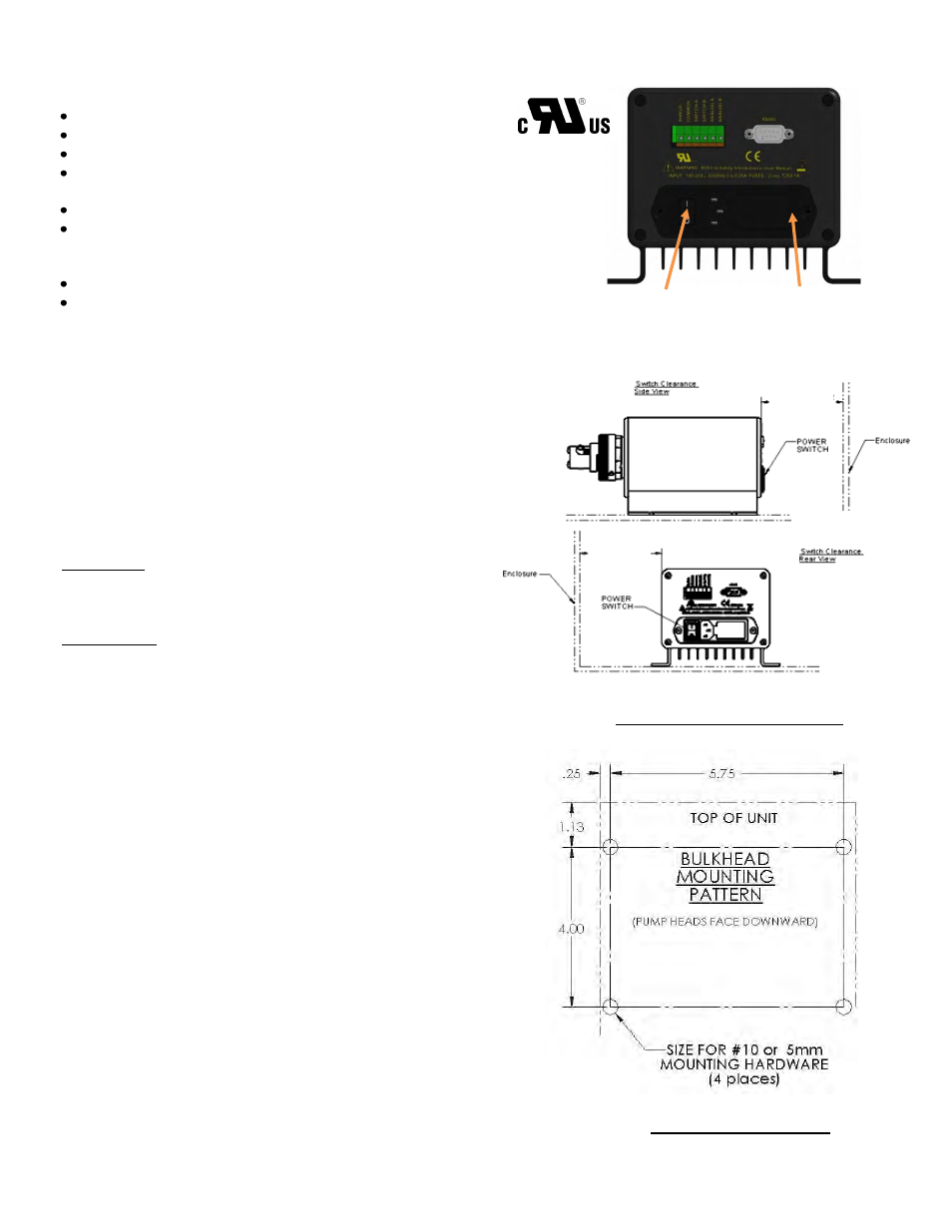
Fuse Location
Power Switch
FEATURES:
“Set and Forget” approach
1-9999 dispenses (adjustable)
Table top/wall mount
Universal power supply with standard IEC line
cord
CSA/UL, CE, RoHS compliant
Learn mode/count to allow customer to command
the PDS-100 to “remember” desired dispense
cycles needed to fill to a desired volume.
Prime Mode
Purge/Reverse Mode
Table-top Mounting: The system is configured for table top
installation initially with rubber grommets slid into the mounting slots.
Before moving on to configuring the control module, make sure that
these rubber grommets are in place. There are no further installation
steps for table top use.
Wall-Mounting: For wall mounting, it is necessary to remove the
four rubber grommets from the control module before attempting to
mount. Each unit must be mounted in the correct orientation; with the
labels facing right side up, the control module will have the pumps at
the bottom. Wall mounting may require an appropriate mounting
board of at least 1/2”(12mm) thickness to straddle the studs of a
typical plasterboard wall. See Figure 3.
IMPORTANT When mounting PDS-100 in an enclosure it is
important to maintain a minimum clearance to provide adequate
space to reach the power switch. See figure 2.
Figure 1
PDS-100 Rear View
Figure 2
Minimum Power Switch Clearance
Figure 3
Required Mounting Pattern
Specifications
Supply Voltage: 100-240VAC +/- 10%, 50/60 Hz. Main Supply
Current: 0.6 to 0.25 Amps. Fuses: T250V-1A (time lag), 5x20mm, 2
required.
Physical: Dimensions: 5" H x 6 1/4" W x 12" (max) D; Weight: 7 lbs
Environment: For indoor use only. Humidity: 80% max for
temperatures up to 31°C, decreasing linearly to 50% relative humidity
at 40°C. Pollution degree, 2. Operating temperatures range from 5ºC
to 40ºC (41ºF to 104ºF).
4.0”
MINIMUM SIDE
CLEARANCE
REQUIRED
4.0”
MINIMUM REAR
CLEARANCE
REQUIRED
Switch Clearance
Rear View
IN-PDS100-13A
11/1/13 HW