Analog input connector and specifications (cont’d) – FMI PDS100 User Manual
Page 12
Page 12 of 18
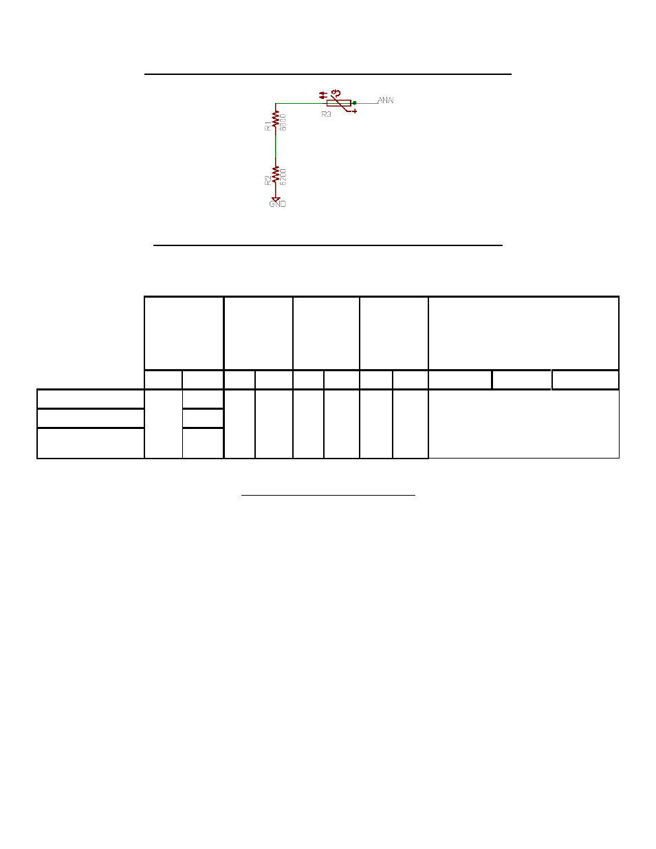
Analog Input Connector and Specifications (cont’d)
Figure 7
Input Resistance Schematic (Analog input: 0 – 5 VDC or 0 – 10 VDC)
RPM
4 - 20 (mA)
Input
resistance
490 ohms
(note 3,1,4)
0 - 5 (VDC)
(note 2,1)
0.5 - 10
(VDC)
(note 2,1)
Analog Input
Min
Max
Min Max Min Max Min Max
4 - 20 mA
0 - 5 VDC
0 - 10 VDC
Standard H Pump
6
750
1.6
20
0.2
5
0.2
10
See Waveforms 1 to 9
Standard Q Pump
600
Standard STQP
Pump
700
Table 2
Input Voltage/Current versus RPM
Note 1:
Maximum current is reduced provided control method is set according to actual
input method (ie 0 – 5 VDC or 0 – 10 VDC). If desired control method is set for
“4–20mA” but a 0 – 5 VDC or 0 – 10 VDC is applied the maximum current will be
at its greatest.
Note 2:
Absolute maximum input voltage is 10.8 VDC
Note 3:
Absolute maximum current is 22 mA
When start/stop is controlled via the analog input the pump(s) will stop when the analog input
goes below the minimum voltage/current. The pumps will run when the minimum voltage/current
is reached and will run at the minimum speed.
IN-PDS100-13A
11/1/13 HW