Analog input connector and specifications – FMI PDS100 User Manual
Page 11
Page 11 of 18
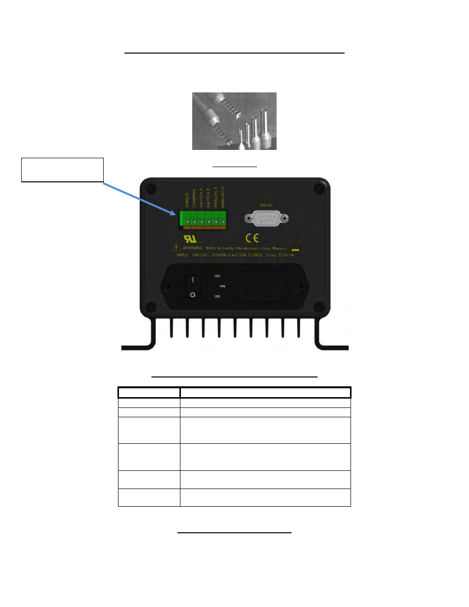
Analog Input Connector and Specifications
The PDS-100 incorporates a simple screwless (spring loaded) terminal strip (see figure 6) for
easy wire (22 to 14 AWG) connection to an external control source such as a PLC. It is
recommended that a DIN wire ferrule be used (See figure 5).
Figure 5
Wire Ferrule
Figure 6
Analog Pump Control Connector (Rear Panel)
Signal
Description
Shield
Cable shield (terminate one end only)
Common
Ground
Switch A
Activates Prime, Purge and Start for Pump A
when connected to Common and configured as
such (TTL open collector or dry contact)
Switch B
Activates Prime, Purge and Start for Pump B
when connected to Common and configured as
such (TTL open collector or dry contact)
Analog A
Controls the speed of Pump A via an external
voltage or current when configured as such
Analog B
Controls the speed of Pump B via an external
voltage or current when configured as such
Table 1
Analog/Switch Input Connector
Analog/Switch Input
Terminal Strip
IN-PDS100-13A
11/1/13 HW