FMI PDS100 User Manual
Page 13
Page 13 of 18
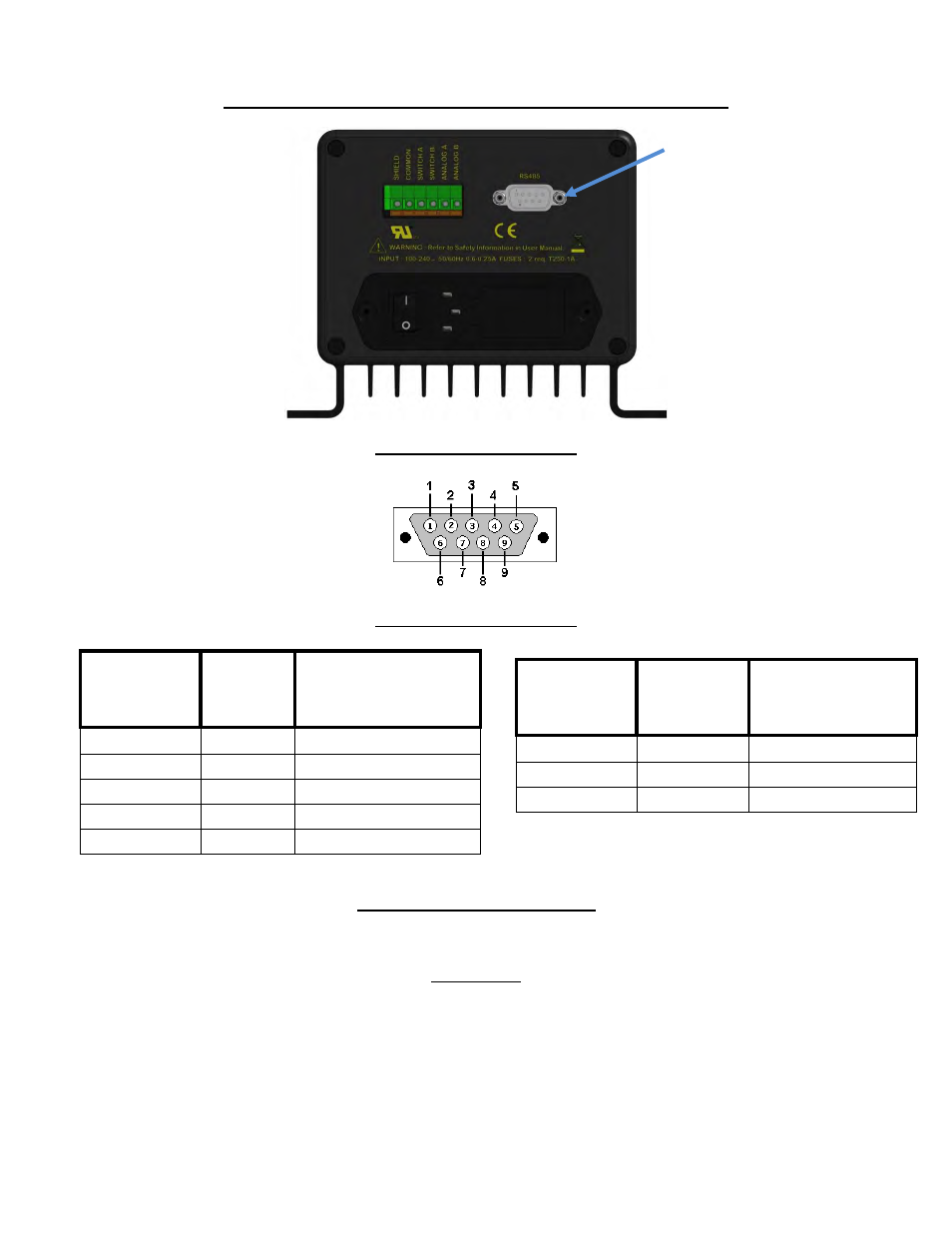
RS485 Connector Pin, command set and specifications
Figure 8
RS485 Control (Rear Panel)
Figure 9
RS485 Control (Rear Panel)
Pin On DB9
Male
Connector
Signal
EIA/TIA-485 name
8
RXD0
A’
4
RXD1
B’
5
TXD1
B
9
TXD0
A
1
Common
C/C’
Table 3
RS485 DB9 pin out assignments
PDS-100 follows the guidelines per MODBUS over Serial Line protocol
Port Settings
Baud Rate
19,200
Stop Bits
1
Data Bits
8
Parity
Even
Pin On DB9
Male
Connector
Signal
EIA/TIA-485 name
5
D1
B | B’
9
D0
A | A'
1
Common
C | C’
RS485 DB9 Male
Connector
(2 wire)
(4 wire)
Important: For all industrial environments, it is recommended that an isolation /surge protection adapter
be used to protect the PDS-100 from external high voltages (for example: Aaxeon UTS-401B-SI.)
IN-PDS100-13A
11/1/13 HW