Cirrus Logic CS8900A User Manual
Cs8900a, Crystal lan ™ ethernet controller, Product data sheet
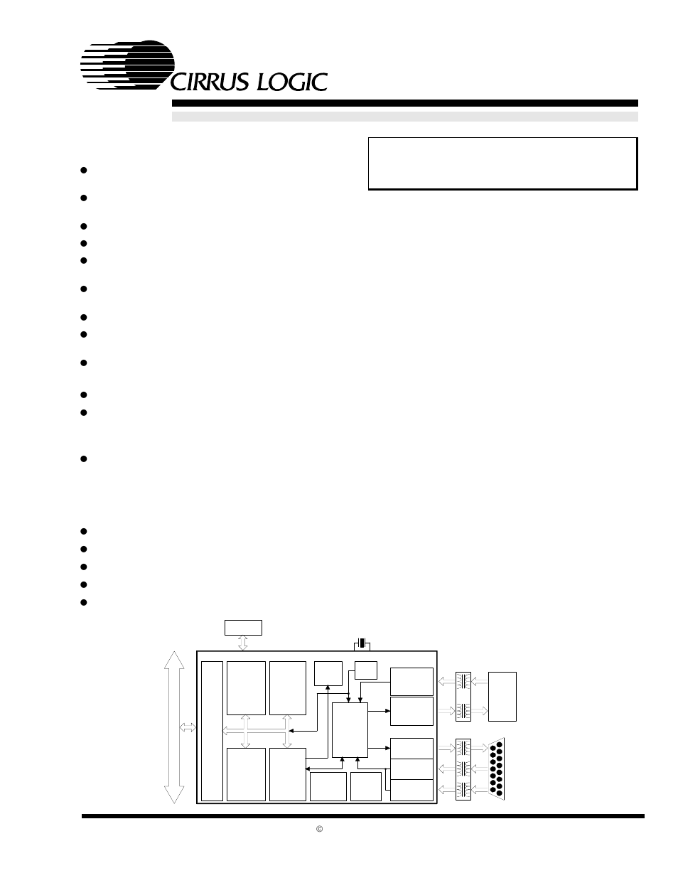
Table of contents
Document Outline
- Features & Description
- 1.0 Introduction
- 2.0 PIN Description
- 3.0 Functional Description
- 3.1 Overview
- 3.2 ISA Bus Interface
- 3.3 Reset and Initialization
- 3.4 Configurations with EEPROM
- 3.5 Programming the EEPROM
- 3.6 Boot PROM Operation
- 3.7 Low-Power Modes
- 3.8 LED Outputs
- 3.9 Media Access Control
- 3.10 Encoder/Decoder (ENDEC)
- 3.11 10BASE-T Transceiver
- 3.12 Attachment Unit Interface (AUI)
- 3.13 External Clock Oscillator
- 4.0 PACKETPAGE Architecture
- 4.1 PacketPage Overview
- 4.2 PacketPage Memory Map
- 4.3 Bus Interface Registers
- 4.4 Status and Control Registers
- 4.5 Initiate Transmit Registers
- 4.6 Address Filter Registers
- 4.7 Receive and Transmit Frame Locations
- 4.8 Eight and Sixteen Bit Transfers
- 4.9 Memory Mode Operation
- 4.10 I/O Space Operation
- Table 18. I/O Mode Mapping
- 4.10.1 Receive/Transmit Data Ports 0 and 1
- 4.10.2 TxCMD Port
- 4.10.3 TxLength Port
- 4.10.4 Interrupt Status Queue Port
- 4.10.5 PacketPage Pointer Port
- 4.10.6 PacketPage Data Ports 0 and 1
- 4.10.7 I/O Mode Operation
- 4.10.8 Basic I/O Mode Transmit
- 4.10.9 Basic I/O Mode Receive
- 4.10.10 Accessing Internal Registers
- 4.10.11 Polling the CS8900A in I/O Mode
- 5.0 Operation
- 5.1 Managing Interrupts and Servicing the Interrupt Status Queue
- 5.2 Basic Receive Operation
- 5.2.0.1 Overview
- Figure 20. Frame Reception
- 5.2.1 Terminology: Packet, Frame, and Transfer
- 5.2.2 Receive Configuration
- 5.2.2.1 Configuring the Physical Interface
- Table 19. Physical Interface Configuration
- 5.2.2.2 Choosing which Frame Types to Accept
- Table 20. Frame Acceptance Criteria
- 5.2.2.3 Selecting which Events Cause Interrupts
- Table 21.
- Table 22. Registers 3 and B Interrupt Configuration
- 5.2.2.4 Choosing How to Transfer Frames
- Table 23. Receive Frame Pre-Processing
- 5.2.3 Receive Frame Pre-Processing
- 5.2.4 Held vs. DMAed Receive Frames
- 5.2.5 Buffering Held Receive Frames
- 5.2.6 Transferring Held Receive Frames
- 5.2.7 Receive Frame Visibility
- 5.2.8 Example of Memory Mode Receive Operation
- 5.2.9 Receive Frame Byte Counter
- 5.2.10 Receive Frame Address Filtering
- 5.2.11 Configuring the Destination Address Filter
- 5.2.12 Hash Filter
- 5.2.13 Broadcast Frame Hashing Exception
- 5.3 Receive DMA
- 5.3.1 Overview
- 5.3.2 Configuring the CS8900A for DMA Operation
- 5.3.3 DMA Receive Buffer Size
- 5.3.4 Receive-DMA-Only Operation
- 5.3.5 Committing Buffer Space to a DMAed Frame
- 5.3.6 DMA Buffer Organization
- 5.3.7 RxDMAFrame Bit
- 5.3.8 Receive DMA Example Without Wrap-Around
- 5.3.9 Receive DMA Operation for RxDMA- Only Mode
- 5.4 Auto-Switch DMA
- 5.5 StreamTransfer
- 5.6 Transmit Operation
- 5.6.1 Overview
- 5.6.2 Transmit Configuration
- 5.6.3 Changing the Configuration
- 5.6.4 Enabling CRC Generation and Padding
- 5.6.5 Individual Packet Transmission
- 5.6.6 Transmit in Poll Mode
- 5.6.7 Transmit in Interrupt Mode
- 5.6.8 Completing Transmission
- 5.6.9 Rdy4TxNOW vs. Rdy4Tx
- 5.6.10 Committing Buffer Space to a Transmit Frame
- 5.6.11 Transmit Frame Length
- 5.7 Full duplex Considerations
- 5.8 Auto-Negotiation Considerations
- 6.0 Test
- 7.0 Characteristics/Specifications - Commercial
- 7.1 absolute maximum ratings
- 7.2 recommended operating conditions
- 7.3 DC CHARACTERISTICS
- DC CHARACTERISTICS
- 7.4 SWITCHING CHARACTERISTICS
- Figure 34. 16-Bit I/O Read, IOCHRDY not used
- Figure 35. 16-Bit I/O Read, with IOCHRDY
- SWITCHING CHARACTERISTICS
- Figure 36. 16-Bit Memory Read, IOCHRDY not used
- Figure 37. 16-Bit Memory Read, with IOCHRDY
- SWITCHING CHARACTERISTICS
- Figure 38. 16-Bit DMA Read
- Figure 39. 16-Bit I/O Write
- SWITCHING CHARACTERISTICS
- Figure 40. 16-Bit Memory Write
- Figure 41. 10BASE-T Transmit
- SWITCHING CHARACTERISTICS
- Figure 42. 10BASE-T Receive
- Figure 43. 10BASE-T Link Integrity
- SWITCHING CHARACTERISTICS
- Figure 44. AUI Transmit
- Figure 45. AUI Receive
- Figure 46. AUI Collision
- SWITCHING CHARACTERISTICS
- Figure 47. External Boot PROM Access
- Figure 48. EEPROM
- 7.5 10BASE-T Wiring
- 7.6 AUI Wiring
- 7.7 QUARTZ CRYSTAL REQUIREMENTS
- 8.0 Characteristics/Specifications - Industrial
- 8.1 absolute maximum ratings
- 8.2 recommended operating conditions
- 8.3 DC CHARACTERISTICS
- DC CHARACTERISTICS
- 8.4 SWITCHING CHARACTERISTICS
- Figure 49. 16-Bit I/O Read, IOCHRDY not used
- Figure 50. 16-Bit I/O Read, with IOCHRDY
- SWITCHING CHARACTERISTICS
- Figure 51. 16-Bit Memory Read, IOCHRDY not used
- Figure 52. 16-Bit Memory Read, with IOCHRDY
- SWITCHING CHARACTERISTICS
- Figure 53. 16-Bit DMA Read
- Figure 54. 16-Bit I/O Write
- SWITCHING CHARACTERISTICS
- Figure 55. 16-Bit Memory Write
- Figure 56. 10BASE-T Transmit
- SWITCHING CHARACTERISTICS
- Figure 57. 10BASE-T Receive
- Figure 58. 10BASE-T Link Integrity
- SWITCHING CHARACTERISTICS
- Figure 59. AUI Transmit
- Figure 60. AUI Receive
- Figure 61. AUI Collision
- SWITCHING CHARACTERISTICS
- Figure 62. External Boot PROM Access
- Figure 63. EEPROM
- 8.5 10BASE-T Wiring
- 8.6 AUI Wiring
- 8.7 QUARTZ CRYSTAL REQUIREMENTS
- 9.0 Physical Dimensions
- 10.0 Glossary of Terms
- Table 1. Revision History