Cirrus Logic CS8900A User Manual
Cs8900a, Crystal lan ™ ethernet controller, Product data sheet
Copyright
Cirrus Logic, Inc. 2010
(All Rights Reserved)
CS8900A
Product Data Sheet
Crystal LAN™ Ethernet
Controller
FEATURES
Single-Chip IEEE 802.3 Ethernet Controller with
Direct ISA-Bus Interface
Maximum Current Consumption = 55 mA (5V
Supply)
3 V or 5 V Operation
Industrial Temperature Range
Comprehensive Suite of Software Drivers
Available
Efficient PacketPage™ Architecture Operates in
I/O and Memory Space, and as DMA Slave
Full Duplex Operation
On-Chip RAM Buffers Transmit and Receive
Frames
10BASE-T Port with Analog Filters, Provides:
-
Automatic Polarity Detection and Correction
AUI Port for 10BASE2, 10BASE5 and 10BASE-F
Programmable Transmit Features:
-
Automatic Re-transmission on Collision
-
Automatic Padding and CRC Generation
Programmable Receive Features:
-
Stream Transfer™ for Reduced CPU Overhead
-
Auto-Switch Between DMA and On-Chip Memory
-
Early Interrupts for Frame Pre-Processing
-
Automatic Rejection of Erroneous Packets
EEPROM Support for Jumperless Configuration
Boot PROM Support for Diskless Systems
Boundary Scan and Loopback Test
LED Drivers for Link Status and LAN Activity
Standby and Suspend Sleep Modes
DESCRIPTION
The CS8900A is a low-cost Ethernet LAN Controller op-
timized for the Industry Standard Architecture (ISA) bus
and general purpose microcontroller busses. Its highly-
integrated design eliminates the need for costly external
components required by other Ethernet controllers. The
CS8900A includes on-chip RAM, 10BASE-T transmit
and receive filters, and a direct ISA-Bus interface with
24 mA Drivers.
In addition to high integration, the CS8900A offers a
broad range of performance features and configura-
tionoptions. Its unique PacketPage architecture
automatically adapts to changing network traffic pat-
terns and available system resources. The result is
increased system efficiency.
The CS8900A is available in a 100-pin LQFP package
ideally suited for small form-factor, cost-sensitive Ether-
net applications. With the CS8900A, system engineers
can design a complete Ethernet circuit that occupies
less than 1.5 square inches (10 sq. cm) of board space.
ORDERING INFORMATION
CS8900A-CQZ
0° to 70° C 5V
LQFP-100
Lead free
CS8900A-IQZ -40° to 85° C 5V
LQFP-100
Lead free
CS8900A-CQ3Z 0° to 70° C 3.3V
LQFP-100
Lead free
CS8900A-IQ3Z -40° to 85° C 3.3V
LQFP-100
Lead free
CRD8900A-1
Evaluation Kit
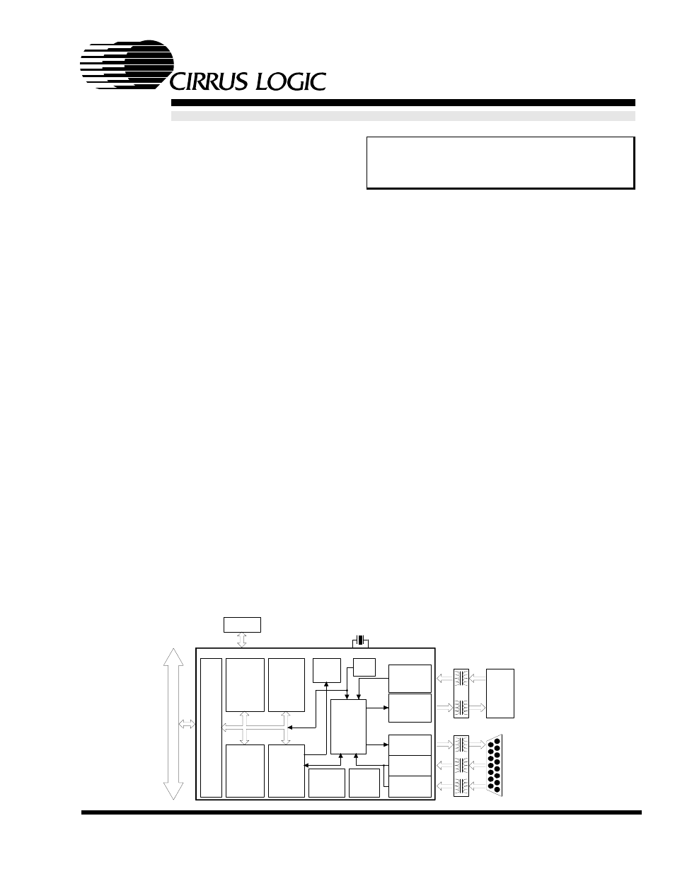
EEPROM
RJ-45
10BASE-T
Attachment
Unit
Interface
(AUI)
20 MHz
XTAL
RAM
Bus
Logic
Memory
Manager
802.3
MAC
Engine
EEPROM
Control
Encoder/
Decoder
&
PLL
10BASE-T
RX Filters &
Receiver
10BASE-T
TX Filters &
Transmitter
AUI
Transmitter
AUI
Collision
AUI
Receiver
Clock
Power
Manager
Boundary
Scan
Test Logic
LED
Control
CS8900A ISA Ethernet Controller
Host
Hos
t B
u
s
DS271F5
SEP ‘10
Document Outline
- Features & Description
- 1.0 Introduction
- 2.0 PIN Description
- 3.0 Functional Description
- 3.1 Overview
- 3.2 ISA Bus Interface
- 3.3 Reset and Initialization
- 3.4 Configurations with EEPROM
- 3.5 Programming the EEPROM
- 3.6 Boot PROM Operation
- 3.7 Low-Power Modes
- 3.8 LED Outputs
- 3.9 Media Access Control
- 3.10 Encoder/Decoder (ENDEC)
- 3.11 10BASE-T Transceiver
- 3.12 Attachment Unit Interface (AUI)
- 3.13 External Clock Oscillator
- 4.0 PACKETPAGE Architecture
- 4.1 PacketPage Overview
- 4.2 PacketPage Memory Map
- 4.3 Bus Interface Registers
- 4.4 Status and Control Registers
- 4.5 Initiate Transmit Registers
- 4.6 Address Filter Registers
- 4.7 Receive and Transmit Frame Locations
- 4.8 Eight and Sixteen Bit Transfers
- 4.9 Memory Mode Operation
- 4.10 I/O Space Operation
- Table 18. I/O Mode Mapping
- 4.10.1 Receive/Transmit Data Ports 0 and 1
- 4.10.2 TxCMD Port
- 4.10.3 TxLength Port
- 4.10.4 Interrupt Status Queue Port
- 4.10.5 PacketPage Pointer Port
- 4.10.6 PacketPage Data Ports 0 and 1
- 4.10.7 I/O Mode Operation
- 4.10.8 Basic I/O Mode Transmit
- 4.10.9 Basic I/O Mode Receive
- 4.10.10 Accessing Internal Registers
- 4.10.11 Polling the CS8900A in I/O Mode
- 5.0 Operation
- 5.1 Managing Interrupts and Servicing the Interrupt Status Queue
- 5.2 Basic Receive Operation
- 5.2.0.1 Overview
- Figure 20. Frame Reception
- 5.2.1 Terminology: Packet, Frame, and Transfer
- 5.2.2 Receive Configuration
- 5.2.2.1 Configuring the Physical Interface
- Table 19. Physical Interface Configuration
- 5.2.2.2 Choosing which Frame Types to Accept
- Table 20. Frame Acceptance Criteria
- 5.2.2.3 Selecting which Events Cause Interrupts
- Table 21.
- Table 22. Registers 3 and B Interrupt Configuration
- 5.2.2.4 Choosing How to Transfer Frames
- Table 23. Receive Frame Pre-Processing
- 5.2.3 Receive Frame Pre-Processing
- 5.2.4 Held vs. DMAed Receive Frames
- 5.2.5 Buffering Held Receive Frames
- 5.2.6 Transferring Held Receive Frames
- 5.2.7 Receive Frame Visibility
- 5.2.8 Example of Memory Mode Receive Operation
- 5.2.9 Receive Frame Byte Counter
- 5.2.10 Receive Frame Address Filtering
- 5.2.11 Configuring the Destination Address Filter
- 5.2.12 Hash Filter
- 5.2.13 Broadcast Frame Hashing Exception
- 5.3 Receive DMA
- 5.3.1 Overview
- 5.3.2 Configuring the CS8900A for DMA Operation
- 5.3.3 DMA Receive Buffer Size
- 5.3.4 Receive-DMA-Only Operation
- 5.3.5 Committing Buffer Space to a DMAed Frame
- 5.3.6 DMA Buffer Organization
- 5.3.7 RxDMAFrame Bit
- 5.3.8 Receive DMA Example Without Wrap-Around
- 5.3.9 Receive DMA Operation for RxDMA- Only Mode
- 5.4 Auto-Switch DMA
- 5.5 StreamTransfer
- 5.6 Transmit Operation
- 5.6.1 Overview
- 5.6.2 Transmit Configuration
- 5.6.3 Changing the Configuration
- 5.6.4 Enabling CRC Generation and Padding
- 5.6.5 Individual Packet Transmission
- 5.6.6 Transmit in Poll Mode
- 5.6.7 Transmit in Interrupt Mode
- 5.6.8 Completing Transmission
- 5.6.9 Rdy4TxNOW vs. Rdy4Tx
- 5.6.10 Committing Buffer Space to a Transmit Frame
- 5.6.11 Transmit Frame Length
- 5.7 Full duplex Considerations
- 5.8 Auto-Negotiation Considerations
- 6.0 Test
- 7.0 Characteristics/Specifications - Commercial
- 7.1 absolute maximum ratings
- 7.2 recommended operating conditions
- 7.3 DC CHARACTERISTICS
- DC CHARACTERISTICS
- 7.4 SWITCHING CHARACTERISTICS
- Figure 34. 16-Bit I/O Read, IOCHRDY not used
- Figure 35. 16-Bit I/O Read, with IOCHRDY
- SWITCHING CHARACTERISTICS
- Figure 36. 16-Bit Memory Read, IOCHRDY not used
- Figure 37. 16-Bit Memory Read, with IOCHRDY
- SWITCHING CHARACTERISTICS
- Figure 38. 16-Bit DMA Read
- Figure 39. 16-Bit I/O Write
- SWITCHING CHARACTERISTICS
- Figure 40. 16-Bit Memory Write
- Figure 41. 10BASE-T Transmit
- SWITCHING CHARACTERISTICS
- Figure 42. 10BASE-T Receive
- Figure 43. 10BASE-T Link Integrity
- SWITCHING CHARACTERISTICS
- Figure 44. AUI Transmit
- Figure 45. AUI Receive
- Figure 46. AUI Collision
- SWITCHING CHARACTERISTICS
- Figure 47. External Boot PROM Access
- Figure 48. EEPROM
- 7.5 10BASE-T Wiring
- 7.6 AUI Wiring
- 7.7 QUARTZ CRYSTAL REQUIREMENTS
- 8.0 Characteristics/Specifications - Industrial
- 8.1 absolute maximum ratings
- 8.2 recommended operating conditions
- 8.3 DC CHARACTERISTICS
- DC CHARACTERISTICS
- 8.4 SWITCHING CHARACTERISTICS
- Figure 49. 16-Bit I/O Read, IOCHRDY not used
- Figure 50. 16-Bit I/O Read, with IOCHRDY
- SWITCHING CHARACTERISTICS
- Figure 51. 16-Bit Memory Read, IOCHRDY not used
- Figure 52. 16-Bit Memory Read, with IOCHRDY
- SWITCHING CHARACTERISTICS
- Figure 53. 16-Bit DMA Read
- Figure 54. 16-Bit I/O Write
- SWITCHING CHARACTERISTICS
- Figure 55. 16-Bit Memory Write
- Figure 56. 10BASE-T Transmit
- SWITCHING CHARACTERISTICS
- Figure 57. 10BASE-T Receive
- Figure 58. 10BASE-T Link Integrity
- SWITCHING CHARACTERISTICS
- Figure 59. AUI Transmit
- Figure 60. AUI Receive
- Figure 61. AUI Collision
- SWITCHING CHARACTERISTICS
- Figure 62. External Boot PROM Access
- Figure 63. EEPROM
- 8.5 10BASE-T Wiring
- 8.6 AUI Wiring
- 8.7 QUARTZ CRYSTAL REQUIREMENTS
- 9.0 Physical Dimensions
- 10.0 Glossary of Terms
- Table 1. Revision History