3 receive dma, 1 overview, 2 configuring the cs8900a for dma operation – Cirrus Logic CS8900A User Manual
Page 90: Table 27. receive dma registers, Receive dma, Cs8900a
90
DS271F5
CS8900A
Crystal LAN™ Ethernet Controller
CIRRUS LOGIC PRODUCT DATASHEET
5.3 Receive DMA
5.3.1 Overview
The CS8900A supports a direct interface to
the host DMA controller allowing it to transfer
receive frames to host memory via slave DMA.
The DMA option applies only to receive
frames, and not transmit operation. The
CS8900A offers three possible Receive DMA
modes:
1) Receive-DMA-only mode: All receive
frames are transferred via DMA.
2) Auto-Switch DMA: DMA is used only when
needed to help prevent missed frames.
3) StreamTransfer: DMA is used to minimize
the number of interrupts to the host.
This section provides a description of Receive-
DMA-only mode. Section 5.4 on page 94 de-
scribes Auto-Switch DMA and Section 5.5 on
page 96 describes StreamTransfer.
5.3.2 Configuring the CS8900A for DMA
Operation
The CS8900A interfaces to the host DMA con-
troller through one pair of the DMA request/ac-
knowledge pins (see Section 3.2 on page 18
for a description of the CS8900A's DMA inter-
face).
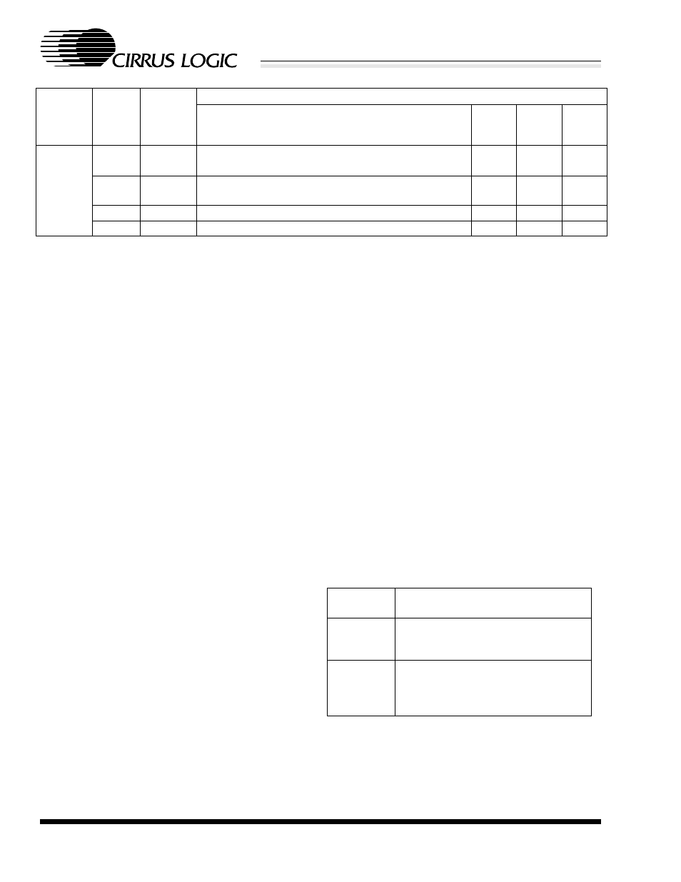
Four 16-bit registers are used for DMA opera-
tion. These are described in Table 27.
Receive-DMA-only mode is enabled by setting
the RxDMAonly bit (Register 3, RxCFG, Bit 9).
Note: If the RxDMAonly bit and the AutoRxD-
MAE bit (Register 3, RxCFG, Bit A) are both
set, then RxDMAonly takes precedence, and
the CS8900A is in DMA mode for all receive
frames.
Broad-
cast
Address
no
yes
(Note 6)
ExtraData Runt CRC Error Broadcast Individual Adr
1
1
0
(actual value X00010)
no
yes
(Note 7)
ExtraData Runt CRC Error Broadcast Individual Adr
0
1
0
no
no
ExtraData Runt CRC Error Broadcast Individual Adr
0
1
0
yes
don’t care ExtraData Runt CRC Error Broadcast Individual Adr
0
0
0
Address
Type of
Received
Frame
Erred
Frame?
Passes
Hash
Filter?
Contents of RxEvent
Bits F-A
Bit 9
Hashed
Bit 8
RxOK
Bit 6
IAHash
Notes: 6. Broadcast frames are accepted as Multicast frames if and only if all the following conditions are met
simultaneously:
a) the Logical Address Filter is programmed as: (MSB) 0000 8000 0000 0000h (LSB). Note that this
LAF value corresponds to a Multicast Addresses of both all 1s and 03-00-00-00-00-01.
b) the Rx Control Register (register 5) is programmed to accept IndividualA, MulticastA, RxOK-only,
and the following address filters were enabled: IAHashA and BroadcastA.
7. NOT (Note 1).
Table 26. Contents of RxEvent Upon Various Conditions
PacketPage
Address
Register Description
0024h
DMA Channel Number: DMA chan-
nel number (0, 1, or 2) that defines the
DMARQ/DMACK pin pair used.
0026h
DMA Start of Frame: 16-bit value that
defines the offset from the DMA base
address to the start of the most
recently transferred received frame.
Table 27. Receive DMA Registers