Table 23. receive frame pre-processing, 3 receive frame pre-processing, 1 destination address filtering – Cirrus Logic CS8900A User Manual
Page 82: 2 early interrupt generation, 22 de, Cs8900a
82
DS271F5
CS8900A
Crystal LAN™ Ethernet Controller
CIRRUS LOGIC PRODUCT DATASHEET
mine how frames will be transferred to host
memory, as described in Table 23.
5.2.3 Receive Frame Pre-Processing
The CS8900A pre-processes all receive
frames using a four step process:
1) Destination Address filtering;
2) Early Interrupt Generation;
3) Acceptance filtering; and,
4) Normal Interrupt Generation.
Figure 21 provides a diagram of frame pre-
processing.
5.2.3.1 Destination Address Filtering
All incoming frames are passed through the
Destination Address filter (DA filter). If the
frame's DA passes the DA filter, the frame is
passed on for further pre-processing. If it fails
the DA filter, the frame is discarded. See
Section 5.2.10 on page 87 for a more detailed
description of DA filtering.
5.2.3.2 Early Interrupt Generation
The CS8900A support the following two early
interrupts that can be used to inform the host
that a frame is being received:
•
RxDest: The RxDest bit (Register C, BufE-
vent, Bit F) is set as soon as the Destina-
tion Address (DA) of the incoming frame
passes the DA filter. If the RxDestiE bit
(Register B, BufCFG, bit F) is set, the
CS8900A generates a corresponding inter-
rupt. Once RxDest is set, the host is al-
lowed to read the incoming frame's DA (the
first 6 bytes of the frame).
•
Rx128: The Rx128 bit (Register C, BufE-
vent, Bit B) is set as soon as the first 128
bytes of the incoming frame have been re-
ceived. If the Rx128iE bit (Register B, Buf-
CFG, bit B) is set, the CS8900A generates
a corresponding interrupt. Once the Rx128
bit is set, the RxDest bit is cleared and the
host is allowed to read the first 128 bytes of
the incoming frame. The Rx128 bit is
cleared by the host reading the BufEvent
register (either directly or through the Inter-
rupt Status Queue) or by the CS8900A de-
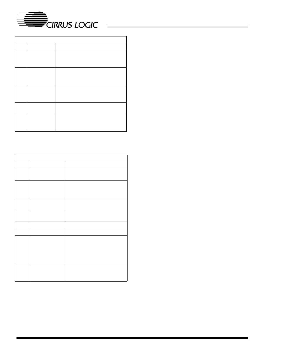
Register B, BufCFG
Bit Bit
Name
Operation
7
RxDMAiE
When set, there is an interrupt if
one or more frames are trans-
ferred via DMA.
A
RxMissiE
When set, there is an interrupt if a
frame is missed due to insufficient
receive buffer space.
B
Rx128iE
When set, there is an interrupt
after the first 128 bytes of receive
data have been buffered.
D
MissOvfloiE When set, there is an interrupt if
the RxMISS counter overflows.
F
RxDestiE
When set, there is an interrupt
after the DA of an incoming frame
has been buffered.
Table 22. Registers 3 and B Interrupt Configuration
Register 3, RxCFG
Bit Bit
Name
Operation
7
StreamE
When set, Stream Transfer
enabled.
9
RxDMAonly
When set, DMA slave opera-
tion used for all receive
frames.
A
AutoRX DMAE When set, Auto-Switch DMA
enabled.
B
BufferCRC
When set, the received CRC
is buffered.
Register 17, BusCTL
Bit
Bit Name
Operation
B
DMABurst
When set, DMA operations
hold the bus for up to approx-
imately 28 µs. When clear,
DMA operations are continu-
ous.
D
RxDMAsize
When set, DMA buffer size is
64 Kbytes. When clear, DMA
buffer size is 16 Kbytes.
Table 23. Receive Frame Pre-Processing