Figure 3. voltage channel — high-voltage input, Cdb5484u – Cirrus Logic CDB5484U User Manual
Page 7
CDB5484U
DS919DB5
7
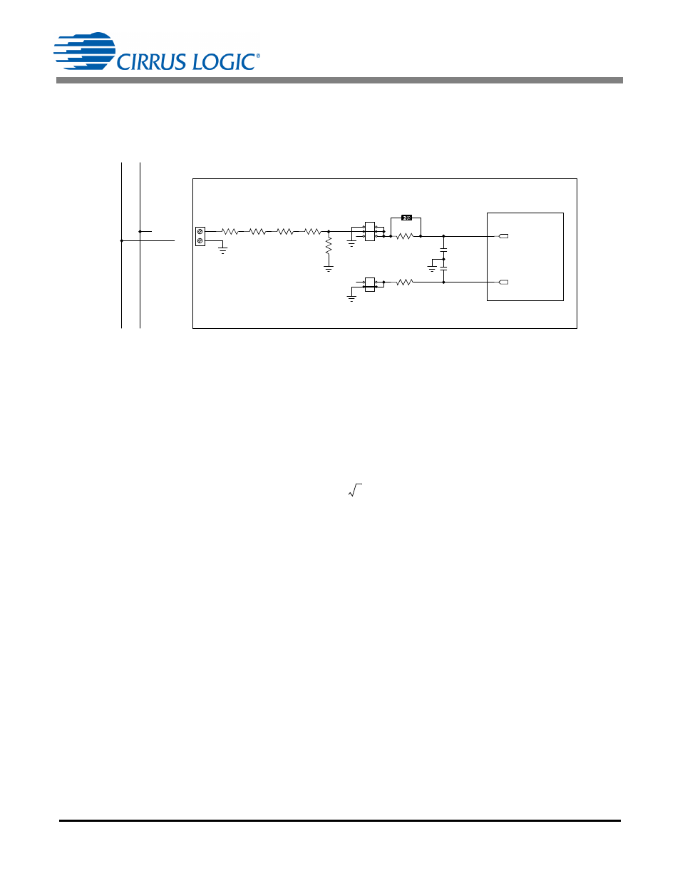
The CDB5484U evaluation board provides screw-type terminals (J4 and J5) to connect high-voltage line
inputs. By installing jumpers on J6 to position LINE1, J10 to position LINE2, J11 to position GND, and J9
to position GND, the input voltage signal is supplied from the high-voltage inputs. Extreme care should be
used when connecting high-voltage signals to the CDB5484U evaluation board (see Figure 3).
Figure 3. Voltage Channel — High-voltage Input
The default attenuation networks provide the following attenuation:
With the CS5484 input range of 250mVp at a maximum AC line input of:
is acceptable. It is recommended to apply a 10% margin for the AC line input (270Vrms).
The CDB5484U evaluation board provides input shorting options for calibration and noise performance
measurements. With a jumper on J6, J11, J10, and J9 in the GND position, the inputs are connected to
analog ground (GND).
GND
LINE1/LINE2
CS5484
CDB5484U
NEU
TRA
L
LI
N
E
J4/J5
J11/J9
J6/J10
R5/R10
1K
C9/C7
0.027UF
C4/C8
0.027UF
R7/
R3 1K
R6/
R4 1K
R8/
R16
422K
R12/
R17
422K
R14/
R18
422K
R15/
R19
422K
J45/J47
VIN1-/VIN2-
VIN1+/VIN2+
1k
4 422k
1k
+
----------------------------------------
1
1689
-------------
=
300Vrms
250mVp
2
----------------------- 1689
=