6 typical sensor connections, 1 shunt power meter example, Figure 6. shunt sensor power meter – Cirrus Logic CDB5484U User Manual
Page 12: Cdb5484u
CDB5484U
12
DS919DB5
1.6
Typical Sensor Connections
The CDB5484U evaluation board provides connections directly to different types of sensors. Flexible on-
board filter networks provide a convenient configuration for three common transducers: current shunt, cur-
rent transformer (CT), or Rogowski coil.
1.6.1
Shunt Power Meter Example
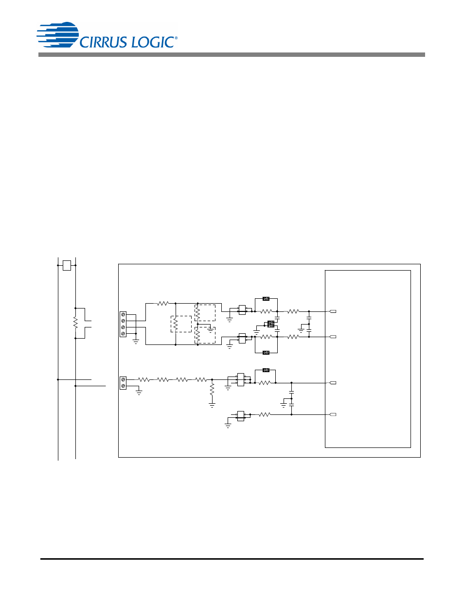
An inexpensive current shunt configuration is easily achievable with the CDB5484U evaluation board.
Figure 6 depicts the voltage and current connections for a shunt sensor and its associated filter configu-
rations.
It is strongly recommended that a low-side (neutral path) current shunt is used, especially in high-voltage
situations. Make sure that all signals are well connected before the power source is turned on. Extreme
care should be taken when connecting high-voltage signals to the CDB5484U evaluation board.
In this configuration it is unnecessary to use a burden resistor. A single anti-alias filter is all that is required
for the current channel. Below the filter corner frequency, the CS5484 inputs will see the same voltage
that is across the shunt. Therefore the shunt voltage should be kept below the maximum of 50mVp with
I-Channel PGA = 50x. A 10% margin is recommended for the shunt voltage (45mVp).
Figure 6. Shunt Sensor Power Meter
IIN1-/IIN2-
IIN1+/IIN2+
GND
GND
GND
LINE1/LINE2
CS
5484
CDB5484U
PH
AS
E
NEU
TRA
L
J1/J12
J4/J5
J7/J13
J8/J14
J11/J9
J6/J10
R5/R10
1K
C5/C11
0.033UF
C6/C12
0.033UF
C9/C7
0.027UF
C4/C8
0.027UF
R11/R22
NO POP
R1/R21
100
R2/R22
100
R7/
R3 1K
R6/
R4 1K
R9/R23
NO POP
R13/R24
NO POP
R8/
R16
422K
R12/
R17
422K
R14/
R18
422K
R15/
R19
422K
R49/R52
1K
R50/R53
1K
C34/C1
0.033UF
C35/C2
0.033UF
J44/J51
J46/J52
R51/
R54
0
J45/J47
J53/J56
J54/J55
SHUNT
IIN1+/IIN2+
IIN1-/IIN2-
VIN1-/VIN2-
VIN1+/VIN2+