Power modes, 1 normal operation, 2 power down, mclk enabled – Cirrus Logic CS5372A User Manual
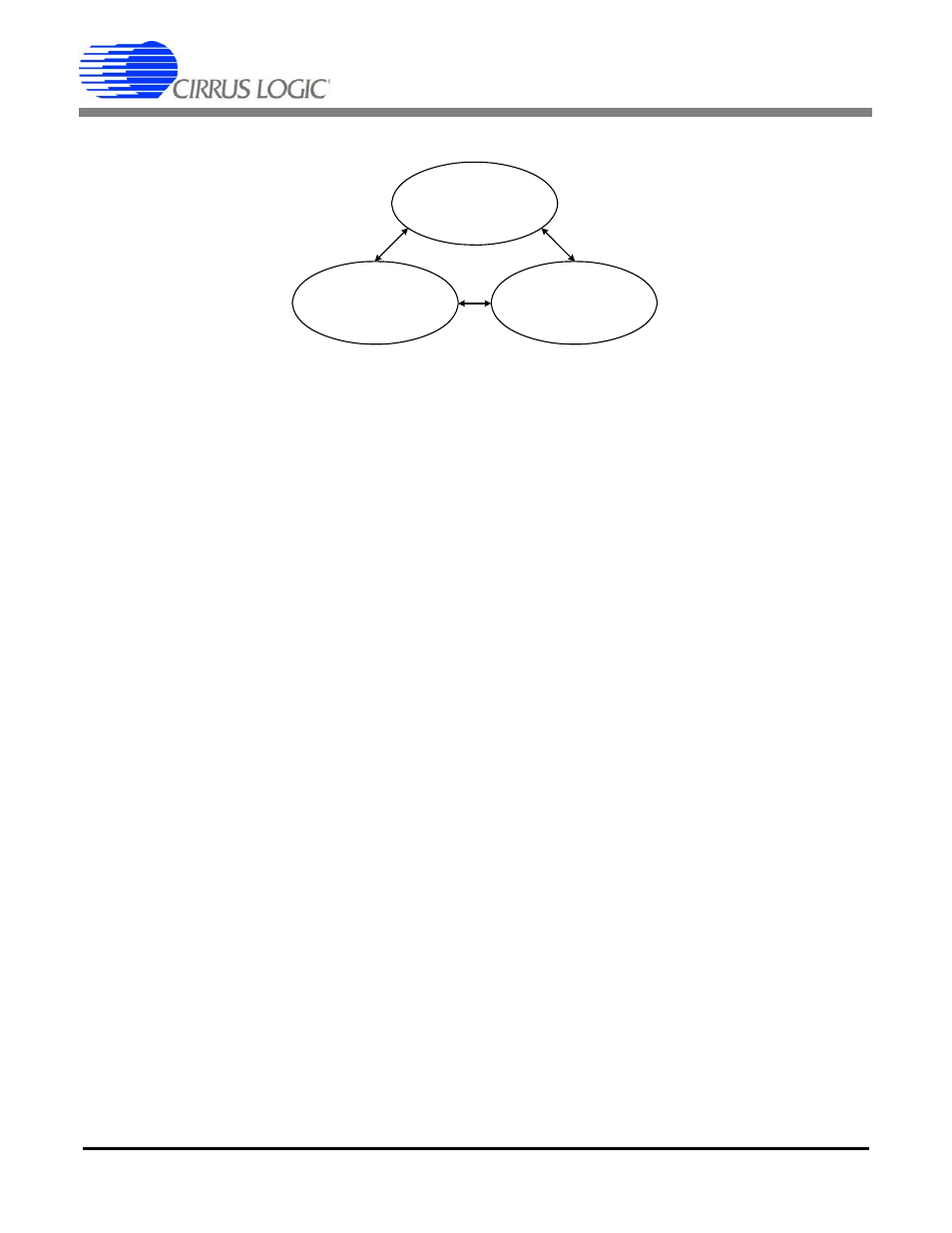
Page 20: 3 power down, mclk disabled, Figure 13. power mode diagram
CS5371A CS5372A
20
DS748F3
6. POWER MODES
The CS5371A and CS5372A modulators have
three power modes. Normal operation, power
down with MCLK enabled, and power down
with MCLK disabled.
6.1 Normal Operation
With MCLK active and the PWDN pin driven
low, the CS5371A and CS5372A modulators
perform normal data acquisition. A differential
analog input signal is converted to an overs-
ampled 1-bit
ΔΣ bit stream at 512 kHz. This ΔΣ
bit stream is then digitally filtered and decimat-
ed by the CS5376A device to a high-precision
24-bit output.
6.2 Power Down, MCLK Enabled
With MCLK active and the PWDN pin driven
high, the CS5371A and CS5372A modulators
are placed into a power-down state. During
this power-down state the modulators are dis-
abled and all outputs are high impedance.
6.3 Power Down, MCLK Disabled
If MCLK is stopped, an internal loss-of-clock
detection circuit automatically places the
CS5371A and CS5372A into a power-down
state. This power-down state is independent of
the PWDN pin setting and is automatically in-
voked after approximately 40
μs without re-
ceiving an incoming MCLK edge.
During this power-down state, the modulators
are disabled and all outputs are high imped-
ance. When used with the CS5376A digital fil-
ter, the CS5371A and CS5372A are in this
power-down state immediately after reset
since MCLK is disabled by default.
NORMAL OPERATION
MCLK = ON
PWDN = 0
POWER DOWN
MCLK = ON
PWDN = 1
POWER DOWN
MCLK = OFF
PWDN = X
Figure 13. Power Mode Diagram