1 operational mode – Cirrus Logic CS485xx User Manual
Page 93
9-13
Copyright 2009 Cirrus Logic, Inc.
DS734UM7
Control
CS485xx Hardware User’s Manual
9.4.1 Operational Mode
The control interface protocol used is determined by the state of the Hardware Strap pins, HS[4:0] which are
sampled at the rising edge of RESET. The HS[4:0] pins should be pulled to VDD or GND using 10 k
Ω
resistors according to the specific control mode desired as shown in
Table 2-1 on page 2- 2
.
The following sections describe the pins used to select the different control modes. For example diagrams of
system connection, please see “Typical Connection Diagrams” on page 1. For information on timing
diagrams and messaging protocol to the CS485xx, please see
Chapter 2, "Operational Modes"
.
Configuration and control of the CS485xx decoder and its peripherals are indirectly executed through a
messaging protocol supported by the operating system (O/S) running on the DSP. In other words, successful
communication can only be accomplished by following the low-level hardware communication format and
high-level messaging protocol. The specifications of the messaging protocol used by the O/S can be found
in AN298, “CS485xx Firmware User’s Manual”. The system designer only needs to read the subsection
describing the communication mode being used. This Manual, the CS485xx Hardware User’s Manual will
explain each communication mode in more detail.
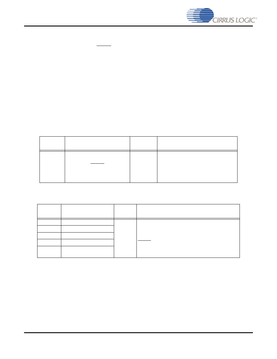
Table 9-7. Reset Pin
LQFP-48
Pin #
Pin Name
Pin Type
Pin Description
2
RESET
Input
Reset, async. active-low Chip Reset
Reset should be low at power-up to
initialize the DSP and to guarantee that the
device is not active during initial power-on
stabilization periods.
Table 9-8. Hardware Strap Pins
LQFP-48
Pin #
Pin Name
Pin Type
Pin Description
32
HS4
Input
Operational Mode Select
Pull-up or Pull-down resistors on these pins set the DSP
operational mode at reset. Hardware Strap Mode Select
The state of these pins is latched at the rising edge of
RESET. The boot ROM uses the state of these pins to
select the boot mode.
31
HS3
26
HS2
27
HS1
20
HS0