Cirrus Logic CS485xx User Manual
Page 12
Overview
CS485xx Hardware User’s Manual
DS734UM7
Copyright 2009 Cirrus Logic, Inc.
1-4
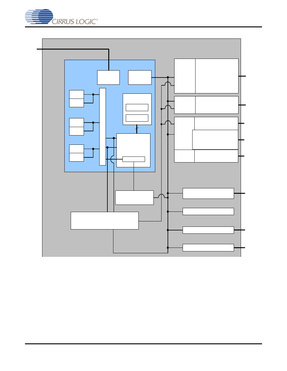
Figure 1-3
illustrates the functional block diagram for CS48520.
Figure 1-3. CS48520 Chip Functional Block Diagram
See AN298, CS485xx Firmware User’s Manual for a list the firmware modules that are available on
CS485xx DSPs.
The audio processing algorithms, post-processing application codes, and/or Cirrus Framework
™
modules
and the associated application notes are available through the Cirrus Software Licensing Program. Standard
post-processing code modules are only available to customers who qualify for the Cirrus Framework™
CS485xx Family DSP Programming Kit. Please refer to the Related Documents section of this manual for
additional application note information.
The CS485xx supports master-mode interface on the serial control port to interface to SPI™ and I
2
C
®
serial
FLASH chips, thus allowing products to be field upgraded as new audio algorithms are developed.
DAI
Controller
Peripheral
Bus
Controller
Log/Exp
Security
Ext (64 bit)
DMA Bus
Peripheral Bus
Y
P
X
P
Y
64 bit
Stereo Audio Output
SPDIF Transmitter
DAO
Controller
ROM
SRAM
Timers
GPIOs
Clock Manager and PLL
Serial Control Port
Debug
Controller
DAO1
Stereo Audio Input/DSD
DAI1
CS48520
Stereo Audio Input
DAI2
DAI
Controller
X
Stereo Audio Output
DMA Controller with 8 Channels
Programmable
Interrupt Controller
Me
m
o
ry C
o
n
tro
lle
r
ROM
SRAM
ROM
SRAM
32-bit Dual Datapath
DSP
with 72-bit
Accumulators
Decryptor
DAO2