1 system block, 1 system block -2, Figure 4-1. adc in / dac out example -2 – Cirrus Logic CDB470xx User Manual
Page 37: Figure 4-2. cdb47xxx system properties -2, Figure 4-1
Running the ADC In / DAC Out Example Application
CDB47xxx User’s Manual
DS886DB11
Copyright 2014 Cirrus Logic, Inc
4-2
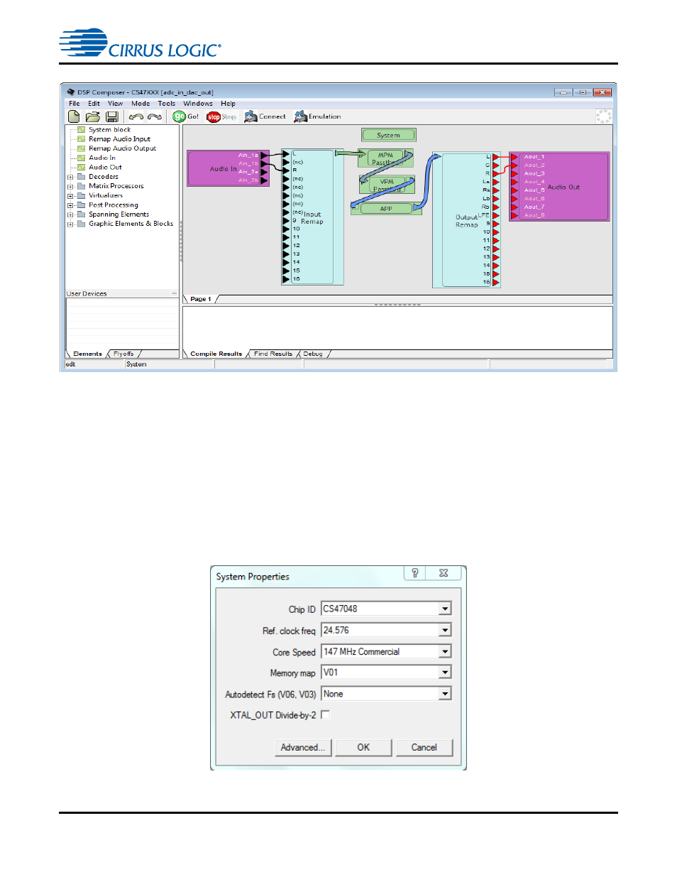
Figure 4-1. ADC In / DAC Out Example
4.2.1 System Block
All designs must contain the System block. In DSP Composer, when you drag the System block onto the
workspace, the dialog box shown in
is displayed. This dialog box provides options for selecting
the Target chip associated with the development board, the Firmware version (memory map), Core
Speed, Reference Clock Frequency (Ref. clock freq.), and the Autodetect Fs.
Note: Leave the Autodetect Fs default value as "None" unless the application note for a specific
firmware module used in a Composer project provides a setting that differs from the default
value.
Figure 4-2. CDB47xxx System Properties
- CobraNet (147 pages)
- CS4961xx (54 pages)
- CS150x (8 pages)
- CS1501 (16 pages)
- CS1601 (2 pages)
- CS1601 (16 pages)
- CS1610 (16 pages)
- CRD1610-8W (24 pages)
- CRD1611-8W (25 pages)
- CDB1610-8W (21 pages)
- CS1610A (18 pages)
- CDB1611-8W (21 pages)
- CDB1610A-8W (21 pages)
- CDB1611A-8W (21 pages)
- CRD1610A-8W (24 pages)
- CRD1611A-8W (25 pages)
- CS1615 (16 pages)
- AN403 (15 pages)
- AN401 (14 pages)
- AN400 (15 pages)
- AN375 (27 pages)
- AN376 (9 pages)
- CRD1615-8W (22 pages)
- CRD1616-8W (23 pages)
- AN402 (14 pages)
- AN404 (15 pages)
- CRD1615A-8W (21 pages)
- CS1615A (16 pages)
- CS1630 (56 pages)
- AN374 (35 pages)
- AN368 (80 pages)
- CRD1630-10W (24 pages)
- CRD1631-10W (25 pages)
- CS1680 (16 pages)
- AN405 (13 pages)
- AN379 (31 pages)
- CRD1680-7W (31 pages)
- AN335 (10 pages)
- AN334 (6 pages)
- AN312 (14 pages)
- AN Integrating CobraNet into Audio Products (16 pages)
- CobraNet Audio Routing Primer (9 pages)
- Bundle Assignments in CobraNet Systems (3 pages)
- CS2300-01 (3 pages)
- CS2000-CP (38 pages)