WIKA CS4S User Manual
Page 33
Operating Instructions Temperature Indicating Controller CS4S
V1.1
•
10/2006
- 33 -
10. Troubleshooting
If any malfunctions occur, refer to the following items, after checking the power supply to the controller.
10.1
Indication
Problem
Presumed cause and solution
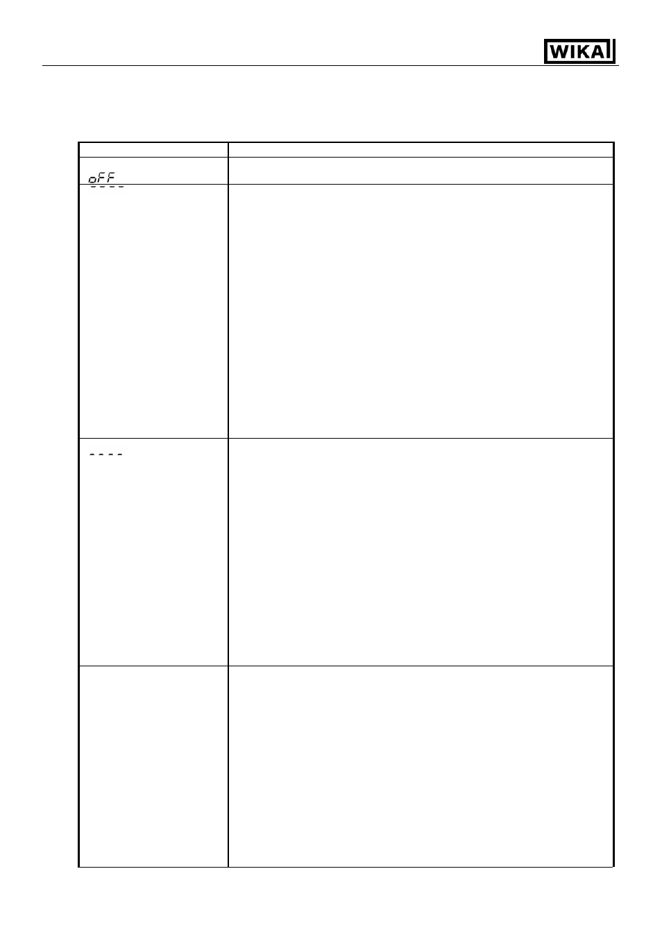
PV display is indicating
[
].
• Control output OFF function is working.
Press the
MODE key for approx. 1 second to release the function.
[
] is blinking on the
PV display.
• Thermocouple, RTD or DC voltage (0 … 1 V DC) is burnt out.
Change each sensor.
How to check sensor burnout
[Thermocouple]
If the input terminal of the instrument is shorted, and if nearby room
temperature is indicated, the instrument should be normal and sensor
may be burnt out.
[RTD]
If approx. 100
Ω of resistance is connected to the input terminals
between A-B of the instrument and between B-B is shorted, then if
nearby 0 °C (32 °F) is indicated, the instrument should be normal and
sensor may be burnt out.
[DC voltage (0 … 1 V DC)]
If the input terminal of the instrument is shorted, and if scaling low limit
value is indicated, the instrument should be normal and the signal wire
may be burnt out.
• Is the input terminal of thermocouple, RTD or DC voltage (0 … 1 V DC)
securely mounted to the instrument input terminal?
Connect the sensor terminals to the instrument input terminals securely.
[
] is blinking on the
PV display.
• Check if input signal source for DC voltage (1 … 5 V DC) or DC current
(4 … 20 mA DC) is normal.
How to check each signal wire
[DC voltage (1 … 5 V DC)]
If the input to the input terminals of the instrument is 1 V DC and if
scaling low limit value is indicated, the instrument should be normal
and the signal wire may be disconnected.
[DC current (4 … 20 mA DC)]
If the input to the input terminals of the instrument is 4 mA DC and if
scaling low limit value is indicated, the instrument should be normal
and the signal wire may be disconnected.
• Is input signal wire for DC voltage (1 … 5 V DC) or DC current
(4 … 20 mA DC) securely connected to the instrument input terminals?
Connect the signal lead wire to the instrument input terminals securely.
• Is polarity of thermocouple or compensating lead wire correct?
Do codes (A, B, B) of RTD agree with the instrument terminals?
Wire them properly.
The PV display keeps
indicating the value which
was set in the Scaling low
limit setting.
• Check if the input signal source for DC voltage (0 … 5 V DC,
0 … 10 V DC) and DC current (0 … 20 mA DC) is normal.
How to check each signal wire
[DC voltage (0 … 5 V DC, 0 … 10 V DC)]
If the input to the input terminals of the instrument is 1 V DC and if the
value corresponding to 1 V DC is indicated, the instrument should be
normal and the signal wire may be disconnected.
[DC current (0 … 20 mA DC)]
If the input to the input terminals of the instrument is 1 mA DC and if
the value corresponding to 1 mA DC is indicated, the instrument
should be normal and the signal wire may be disconnected.
• Are the input lead wire terminals for DC voltage (0 … 5 V DC,
0 … 10 V DC) or DC current (0 … 20 mA DC) securely mounted to the
instrument input terminals?
Mount the sensor terminals to the instrument input terminals securely.