WIKA CS4S User Manual
Page 11
Operating Instructions Temperature Indicating Controller CS4S
V1.1
•
10/2006
- 11 -
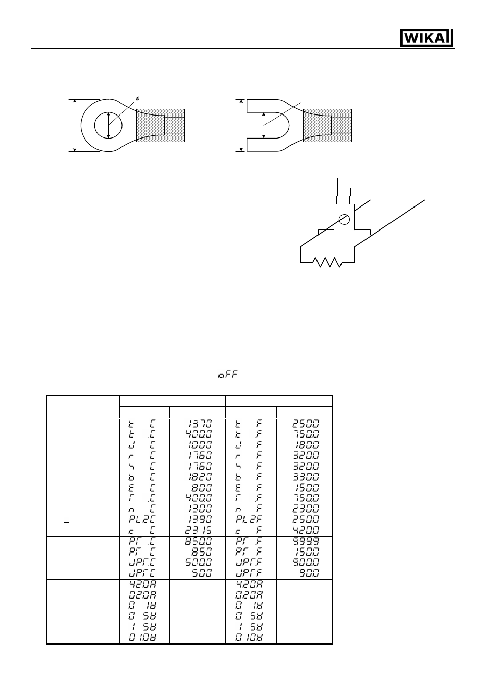
Lead wire solderless terminal
Use a solderless terminal with isolation sleeve that fits in the M3 screw as shown below.
The torque is approximately 0.6 Nm to 1.0 Nm.
(Fig.
4-2)
Option: Heater burnout alarm
(1) This alarm is not available for detecting heater current
under phase control.
(2) Use the current transformer (CT) provided and pass one
lead wire of the heater circuit into the hole of the CT.
(3) When wiring, keep the CT wire away from AC sources
or load wires to avoid the external interference.
(Fig. 4-3)
5. Setup
Wire the power terminals only. After the power is turned on, the sensor input characters and temperature
unit are indicated on the PV display and the input range high limit value is indicated on the SV display for
approximately 3 seconds (Table 5-1).
If any other value is set during the scaling high limit setting, the set value is indicated on the SV display.
During this time, all outputs and the LED indicators are in OFF status. Control will then start and the input
value will be indicated on the PV display and main setting value (SV) will be indicated on the SV display.
(While control output OFF function is working,
is indicated on the PV display.)
(Table 5-1)
°C °F
Sensor input
PV display SV display
PV display
SV display
K
J
R
S
B
E
T
N
PL-
C (W/Re5-26)
Pt100
JPt100
4 … 20 mA DC
0 … 20 mA DC
0 … 1V DC
0 … 5V DC
1 … 5V DC
0 … 10V DC
Scaling high
limit value
Scaling high
limit value
3.2mm
5.8mm or less
3.2mm
5.8mm or less
CT input Terminal
Power
supply
Heater
CT
(11)
(12)