Running, Action explanation – WIKA CS4S User Manual
Page 21
Operating Instructions Temperature Indicating Controller CS4S
V1.1
•
10/2006
- 21 -
6. Running
After the controller has been mounted to the control panel and wiring is completed, it can be started in the
following manner.
(1) Turn the power supply to the CS4S ON.
• For approx. 3s after the power is switched ON, the sensor input character and the temperature unit are
indicated on the PV display and input range high limit value is indicated on the SV display.
See (Table 5-1).
If any other value has been set in the scaling high limit setting, the set value is indicated on the SV display.
During this time, all outputs and LED indicators are in OFF status.
• After that, control starts indicating input value on the PV display, and main setting value on the SV
display.
• While the Control output OFF function is working,
is indicated on the PV display.
(2) Input each setting value.
Input each setting value, referring to “5. Setup”.
(3) Turn the load circuit power ON.
Starts the control action so as to keep the controlled object at the main setting value.
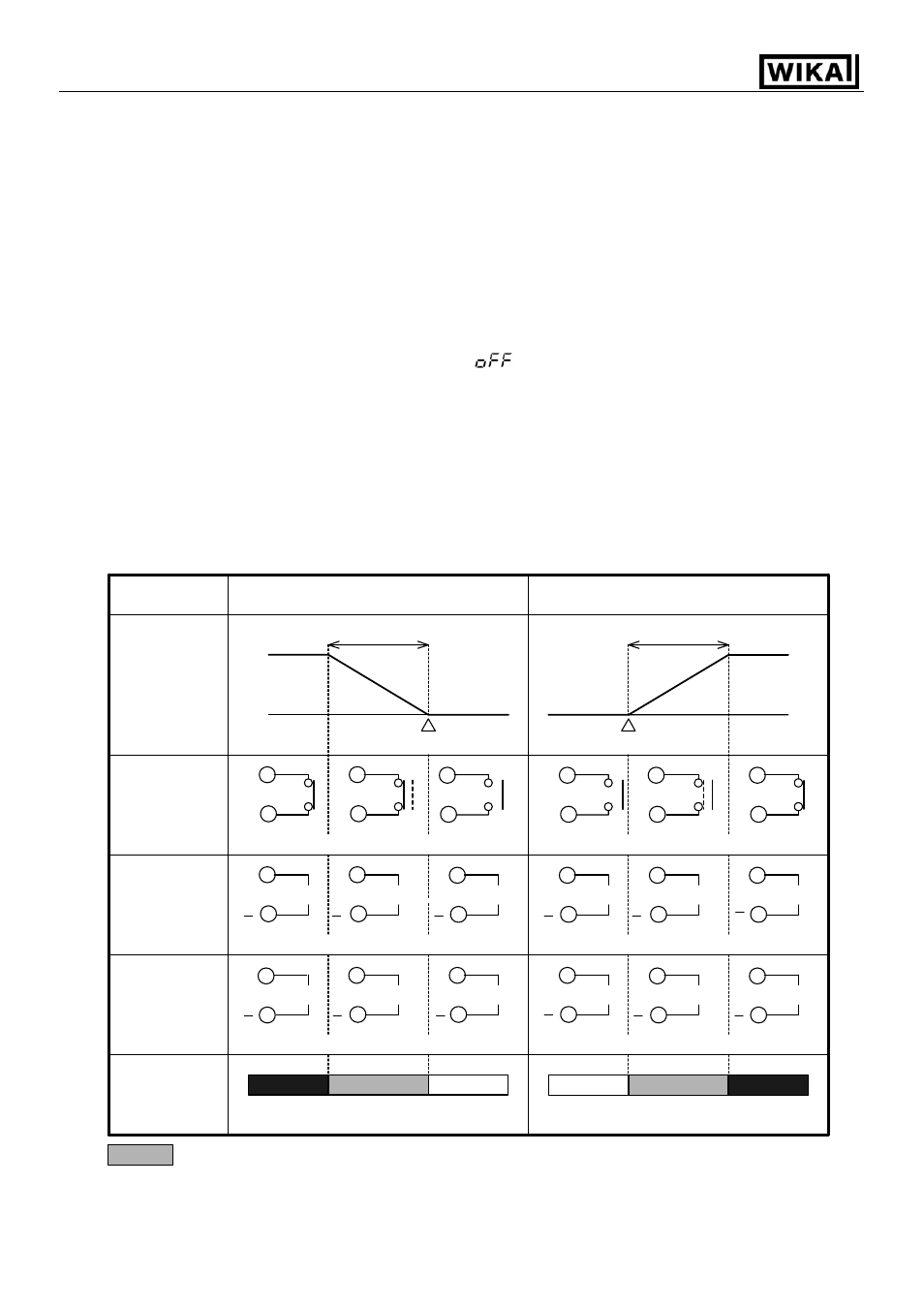
7. Action explanation
7.1 OUT1 action
part : Acts ON or OFF.
Heating (Reverse) action
Cooling (Direct) action
Control
action
Cycle action is performed according to deviation
Control output
relay
Control output
logic level
DC 0/12 V
Changes continuously according to deviation
Control output
analogue
current signal
(4 … 20 mA)
Indication
(OUT1) Green
Lit
Unlit
ON
OFF
SV setting
Proportional band
ON
OFF
DC 0 V
DC 0/12 V
DC 12 V
+
DC 20 mA
DC 20 ... 4 mA
DC 4 ... 20 mA
Proportional band
Lit
DC 0 V
DC 12 V
DC 12/0 V
DC 20 mA
DC 4 mA
Cycle action is performed according to deviation
Cycle action is performed according to deviation
Cycle action is performed according to deviation
Changes continuously according to deviation
+
+
+
+
+
+
+
+
+
+
+
Unlit
DC 4 mA
7
6
7
6
7
6
7
6
7
6
7
6
7
6
7
6
7
6
7
6
7
6
7
6
7
6
7
6
7
6
7
6
7
6
7
6
SV setting