Specifications / 4. design and function, Design and function – WIKA 702.03.100 User Manual
Page 9
GB
2122740.01
3. Specifications / 4. Design and function
For further specifications see the corresponding product label, WIKA data sheet
and the order documentation.
Electrical contact
Type of contact
Micro switch
Contact functions
Single (change-over) contact
850.3
Double (change-over) contact
850.3.3
Load data
Voltage AC
Voltage DC
U max.
250 V
30 V
I max.
5 A
0.4 A
P max.
250 VA
10 W
Switch point setting
from the outside at assistant scale by means of adjustment
screw(s)
Setting range
from 10 % to 100 % of the full scale value
Switch point
reproducibility
≤ 1.6 %
Switch hysteresis
max. 5 % of the full scale value (option: max. 2.5 %)
Electrical connection
via cable gland M20 x 1.5 with 1 m free cable end
WIKA operating instructions differential pressure gauge, model 702.03.100
9
2367781.03 06/2013 GB/D/F/E
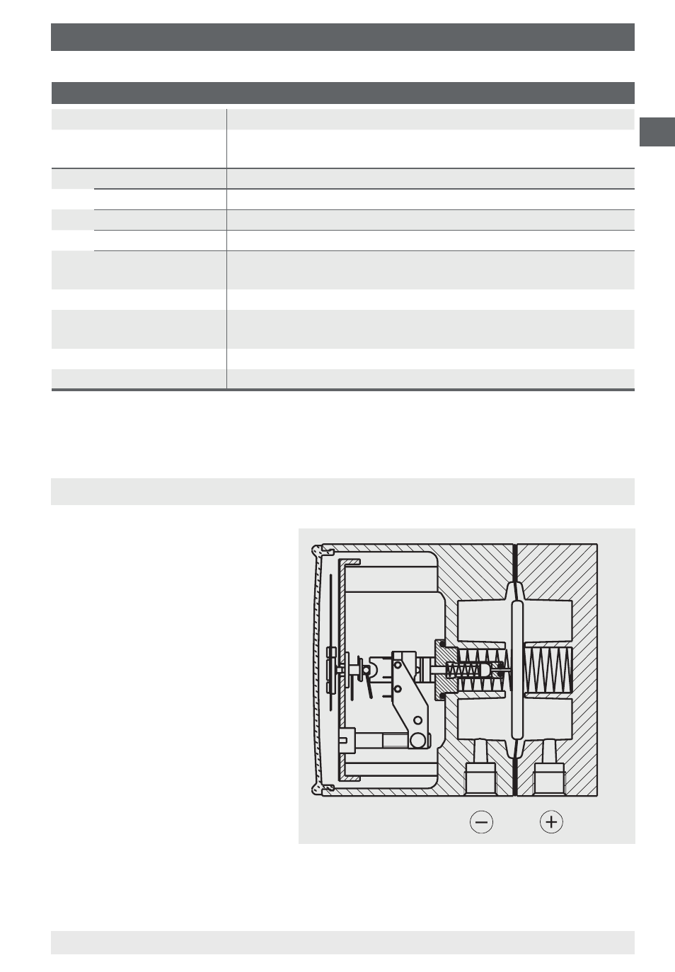
4. Design and function
4.1 Description
The ⊕ and ⊖ media chambers
are separated by an elastic dia-
phragm. The differential pres-
sure leads to an axial deflection
of the the diaphragm against
the measuring range spring.
The deflection, which is
proportional to the differential
pressure, is transmitted to
a movement and in addition
to the plungers of the micro
switches via a pressure-tight
and low friction link.
4.2 Scope of delivery
Cross-check scope of delivery with delivery note.